We are pleased to announce today that we have released Terrain Analysis Package (TAP™) 7.2. This is the second major update to the all-new TAP 7 application that we released in October of 2018. Current TAP 7.1 users should look for the Download Updates button on the main window and use it to install the latest TAP 7.2. TAP 7.2 includes more legacy modules that have been transitioned from the TAP 6 software plus several valuable new features. Click here to view a short video on What’s New in TAP 7.2.
The legacy modules that are now incorporated into TAP 7.2, which are available to TAP licensees with maintenance dates of May 1, 2019 or later, follow:
- Omni Pattern Distortion: The Pattern Distortion module models the horizontal plane pattern distortion of a side mounted, vertically-polarized, omni-directional antenna when mounted on a metal tower structure. It uses the mounting orientation and distance from the tower, as well as the size and type of tower, frequency and nominal gain.
- Stacked Antenna: The Stacked Antenna module adds multiple vertically-stacked horizontal plane directional antenna patterns (with different powers and major lobe azimuths) and calculate an approximate composite pattern.
- Broadcast / SMR Propagation: The Broadcast/SMR module of SoftWright’s Terrain Analysis Package (TAP) uses topographic elevation information to compute height above average terrain (HAAT) from a specified site. This information is used to compute an area contour curves for FM and TV from Part 73 of the FCC Rules as well as Specialized Mobile Radio (SMR) curves by derating the Part 73 curves appropriately per FCC Part 90.
Highlights of the other new features available in TAP 7.2 include:
- Streamlined Licensing: The licensing architecture has been changed to simplify the license activation process. The new architecture requires the user to only activate once per computer regardless of the number of users. As a result, current customers will have to reactivate the first time after upgrading to TAP 7.2.
- Improved Manual Obstructions: The ability to add annotations and obstructions to maps within TAP Mapper has been enhanced to support circles and arbitrary polygon shapes.
- Add Transmission Lines: The transmission lines editor has been upgraded to import from a TAP 6 lines database and to manually add new transmission lines.
- Coverage Layer Template: Users now have the ability to select a layer style template (including levels and colors) that will be automatically applied when loading coverage study results in TAP Mapper.
omni pattern distortion module
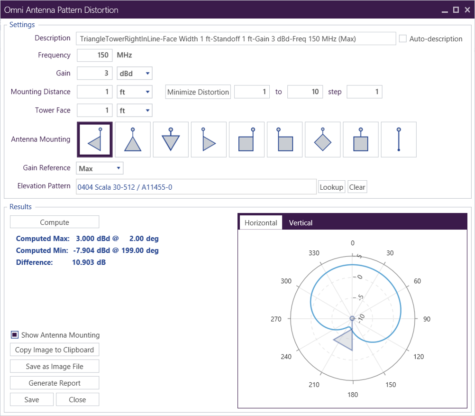
The Omni Pattern Distortion (PD) module allows the user to include the effect of side-mounting an omni-directional antenna on a tower. Launch the Omni Distortion module from the TAP 7 main window UTILITIES tab and then click the Omni Antenna Distortion button.

The Omni Antenna Pattern Distortion form is displayed by the program. This form allows you to enter the parameters for computing the distorted pattern. Enter a description of the antenna and mounting configuration. This description will be used later when you save the antenna to an antenna library for later use. Enter the operating frequency of the antenna. All mounting and antenna spacing values are considered in terms of the wavelength of the operating frequency.
Enter the dimension of the tower face. For self-supporting towers, or other structures of non-uniform cross section, you should enter the width of the tower at the mounting location of the antenna. Select the mounting configuration of the antenna by clicking on the appropriate diagram. You can select any of the nine antenna mounting configurations shown.
When all of the parameters have been set, click the “Compute” button to start the calculation. When the calculation is finished, a table is displayed beneath the Compute button. The table shows the minimum and maximum values of the computed pattern. The difference between these values provides a measure of the distortion introduced. (A perfectly omni-directional pattern would have a difference of zero.) The distorted horizontal directional gain pattern plot is shown in the thumbnail graph on the lower right hand side. Click the “Save” button to save the computed antenna to the database for use in coverage studies or other purposes.
stacked antenna module
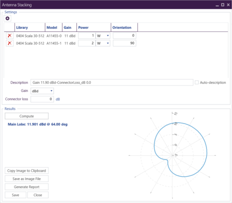
The TAP Stacked Antenna module can compute an estimate of the combined azimuth plane pattern of multiple antennas stacked on a common vertical axis. The Stacked Antenna program combines the horizontal plane patterns of multiple antennas (as many as you want to enter into the program) for a preliminary antenna design. Launch the Stacked Antenna module from the TAP 7 main window Utilities tab and then click the Stacked Antenna button.
The Antenna Stacking window is displayed. This form shows a listing of the antenna patterns to be combined. To add an antenna, click the ‘+’ button. The standard Antenna Manager window appears. Select the Library and then the Model and then click Ok.
The selected antenna is added to the list. You can edit the values of the relative orientation of each antenna individually. You can also edit the power input for each antenna.
When you have finished entering the desired parameters, click the Compute button. The pattern of the stacked array will be computed, including an estimate of the composite gain and the azimuth of the major lobe of the array.
For more information on the new TAP 7.2 or how to update a TAP™ maintenance plan, please call (800) 728-4033 x1 or email sales@softwright.com.