Intermod Setup in HDSpectrum™
Q: How do I set up an intermod study with HDSpectrum?
A: In HDSpectrum, you can open or create a database of frequency information and edit the values, as well as select the settings you want for an intermodulation study in TAP.
(Note that all values and settings in this article are for illustration purposes only. You should determine the appropriate settings for your application using good engineering judgment.)
You have several options for the intermod database to use:
Ø You can create a new database and manually enter the data
Ø You can open an database created with HDSpectrum or other programs
Ø You can open the source file for a previous intermod study created in TAP5 or earlier, or in HDSpectrum
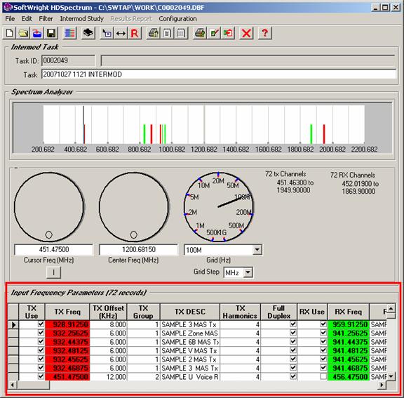
Once the database you want to use for the intermod study is open, the contents will be displayed in the Input Frequency Parameters section of the HDSpectrum form:
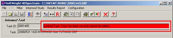
(Note if the task status is marked as “Locked” the
database and intermod study settings cannot be edited. A Task is locked when
it is run to prevent confusion that would result from changing the settings of
a study that has already been computed. If you want to create a new intermod
study with these same settings, click the New button ![]() on the toolbar to create a copy of the
Task.)
on the toolbar to create a copy of the
Task.)
With the database you want to use open, you can edit the values:
Ø TX Use This check box enables you to exclude frequencies from an intermod study without the need to physically remove the record from the database. (You can also use the Edit menu in HDSpectrum to select “All” or “None” of the records to have the “TX Use” field marked. Note you must have at least one record marked in order to save and run the intermod study.)
Ø TX Freq This column is the transmitter carrier frequency in megahertz (MHz).
Ø TX Offset This column is the modulated range above and below the transmitter carrier frequency. If you enter an offset value of zero, the intermod calculations will be done only with the center frequency. The Offset frequency is entered in kilohertz (kHz).
Ø TX Group This value provides an option to assign a group number to transmitter facilities; For example, suppose you want to add a new transmitter frequency to a site and four TX frequencies are being considered. You could run four separate intermod studies, including one of the potential transmitter frequencies in each study. The Group option enables you to run one study including all four and assign the same group number to the frequencies. The program will disregard any hits that would result from any of these four frequencies combining. This eliminates the need to run and evaluate four separate intermod studies. The Group number can be any non-zero value.
Ø TX Desc This column is a description of the transmitter frequency.
Ø TX Harmonics Use the pulldown list, or type a value from 1 to 9 for the number of harmonics to be computed for this transmitter frequency.
Ø Full Duplex Use this checkbox to indicate Full Duplex operation. In Full Duplex mode, the transmitter can be in operation at the same time as the receiver, so it is possible for the transmitter frequency to combine with other frequencies to create an intermod product that interferes with its own receiver frequency. In Half Duplex or Simplex operation this is not a problem, so unchecking the Full Duplex box will avoid computing products that include a receiver’s own transmitter. (You can also use the Edit menu in HDSpectrum to select “All” or “None” of the records to be marked as Full Duplex.)
Ø RX Use This check box enables you to exclude frequencies from an intermod study without the need to physically remove the record from the database. (You can also use the Edit menu in HDSpectrum to select “All” or “None” of the records to have the “RX Use” field marked. Note you must have at least one record marked in order to save and run the intermod study.)
Ø RX Freq This column is the center frequency for the receiver in megahertz.
Ø RX Offset This column is the protected range above and below the receiver center frequency. If you enter an offset value of zero, the intermod calculations will be done only with the center frequency. The Offset frequency is entered in kilohertz (kHz).
Ø RX Desc This column is a description of the receiver frequency.
When you edit values on a record, notice that the selection button at the left of the record displays a small pencil icon, to indicate the record is being edited:
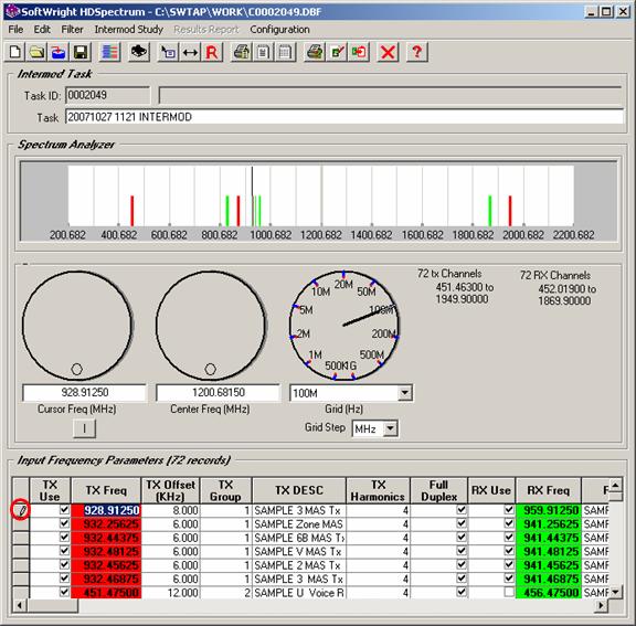
When you move off of the record (with the keyboard up or down arrow to move to another row, or the keyboard tab key to tab from the end of the row to the next row) the changes are saved in the database and the pencil icon disappears.
If you decide you do not want the change you made you can press the keyboard Escape key. As long as the pencil icon is still displayed, the changes in the record have not been written to the database and the Escape key will restore the previous values to the record.
To delete a record, place the mouse text cursor in one of the columns in the row you want to delete, then click the selection button to the left of the record to highlight the entire row.
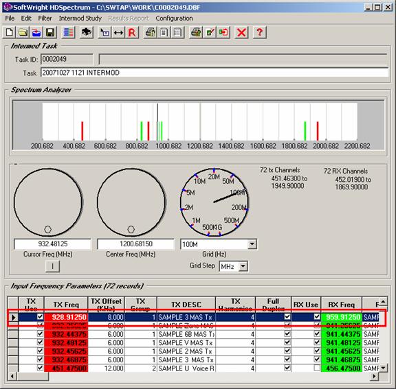
Then press the Delete key on the keyboard. Note that deleted records cannot be recovered.
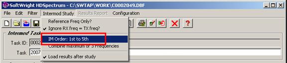
The Intermod Study menu in HDSpectrum gives you access to other settings for the intermod study:
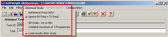
Ø Reference Freq Only? This option enables you to limit the intermod products computed to only that include specific transmitter frequencies, marked as “Reference Frequencies” as described below.
Think of two different approaches to an intermod study. A “diagnostic” study examines products for all the transmit facilities for which the “TX Use” field is marked. This would be the approach you might want to use if you are running an intermod study for the first time for a site where intermod problems exist and you want to examine all possible products resulting from any of the transmitter frequencies. Examining all possible frequency combinations would show the possible intermod products that you can examine to try to isolate and solve the existing problems.
On the other hand, a “preventative” study might want to examine only certain transmitter combinations. For example, suppose you have a site which is free of intermod problems (no, really, try to imagine it!). If a new transmitter frequency is to be added at the site, it would be helpful to run an intermod study that looks only at any possible intermod products that involve that new frequency. Intermod products could probably be computed using existing frequencies at the site, but if that product is not actually a real-world problem, it is not relevant for the evaluation of the new transmitter frequency.
The “Reference freq only” option enables you to select only certain frequencies to include in the intermod study products that are reported. For example, suppose the site has transmitter frequencies A, B, and C, all operating and no intermod problems have been experienced. In that case, the intermod product of A + 2B would not be of interest, since the mathematical possibility of the product has not been realized in an actual problem. But if frequencies D and E are to be added, we would want to examine any combination involving D and/or E that creates an intermod product that could possibly interfere with a receiver frequency at the site. In that case we could mark D and E as reference frequencies. The intermod study would ignore any combinations that do not involve D or E (only, A, B, and C). But any combination with D and or E, along with any of the existing A, B, or C frequencies would be reported.
When the “Reference Freq Only” menu is selected, an additional column is displayed in the Input Frequency Parameters information section of the form.
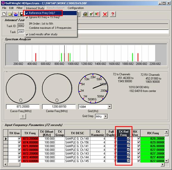
Mark the check-box in this column for any frequency you want to include in the list of “reference frequencies”. Only computed intermod products that include one of the marked reference frequencies will be computed and reported. Since many combinations of non-reference frequencies will not be considered, the intermod study will run faster in this configuration.
Ø Ignore RX freq = TX freq? If you have a database in which some receiver frequencies equal transmitter frequencies in different records, you can mark this menu item with a check to ignore any intermod products involving the transmitter and receiver on the same frequency. For example, if all of your transmitter frequencies are in separate records from receiver frequencies, you might have a simplex frequency pair using the same frequency value. Since the transmitter and receiver frequencies are in different records, the program will not ignore the combination (as it does for values in the same record – unless it is a Full Duplex record). Setting the check mark in the menu will cause the program to ignore the circumstance of equal transmitter and receiver frequencies in different records.
Ø IM Order The "order" of the product is the sum of the harmonic values for each of the transmit frequencies combined in the intermod product. For example, an intermod product generated from the second harmonic of transmitter frequency A, and the fundamental frequencies of B and C (2xA + B – C) is a fourth order product (2 + 1 + 1). If you specified up to a 9th harmonic for four transmitters used in a particular study, a 36th order product is mathematically possible (9xA + 9xB – 9xC + 9xD). However, such a product is generally unlikely to be of practical significance. A typical intermod study will analyze products up to the 5th order. Product orders in excess of five are generally considered to be of less practical importance and will increase execution time.
When you click the IM Order menu, you will be prompted for the minimum and maximum intermod order values to include in the study.
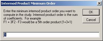
Note two separate forms are displayed, one for the starting order value, one for the maximum order value:
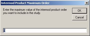
After setting the values, the new settings are shown in the menu:
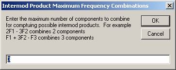
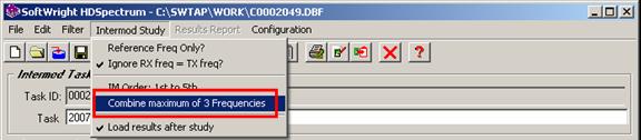
Ø Combine maximum This menu item shows the maximum number of frequencies to be combined for computing potential intermod products. You can direct TAP to combine up to four transmitter harmonics into a calculated intermod product. If you specify a maximum equal to 1, the harmonics of each transmitter will be examined one at a time. It is typically sufficient to study a maximum of three combinations. Four combinations may result in resultant products considered too remote for practical purposes, and will significantly increase processing time for the study.
When you click the “Combine maximum” menu you will be prompted for the number of frequencies to combine for the study
When you enter a new value, it will be displayed in the menu:
You can save the intermod study by clicking the Save
button ![]() on the
toolbar:
on the
toolbar:

Remember that the changes to the intermod database are saved as soon as you move off the record you are changing. The Save button saves the Task information and the intermod study settings.
To start the execution of the intermod study, click the
Run button ![]() on
the toolbar:
on
the toolbar:
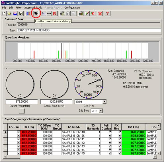
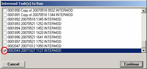
A list of available Intermod Tasks (which have not yet been run) will be displayed. Mark the checkbox for the Task(s) you want to run and click the Continue button. Marking several studies you have created enables you to run them in a batch mode.
|
|
Copyright 2006 by SoftWright LLC