Adjacent Channel Interference
SoftWright Home
Q: How can I compute an interference study using receiver rejection specifications that are a function of the receive signal strength?
A: With TAP6.0.2437 or later and a Maintenance Subscription date of February 29, 2012, or later, with the TAP Adjacent Channel Interference module, you can set up very flexible specifications for a receiver based on the received power of the desired signal, and the frequency offset of the undesired signals. Those receiver rejection specifications are used to determine which locations will have service and which locations will not due to interfering signals.
Note that all values in this example are for demonstration purposes only. You should determine appropriate settings for your application.
This article describes:
· Introduction to Adjacent Channel Interference Studies in TAP
· Setting up Receiver Rejection Specifications
o Specification with one channel value
o Specification with multiple channel values
o Specification with multiple desired signal levels
· Adjacent Channel Interference study setup
· Adjacent Channel Interference calculations
Introduction
Next Section
The Terrain Analysis Package (TAP)™ Adjacent Channel Interference study enables you to compute the interfering effects between stations.
· First, you will compute the field strength for a Desired signal (D) over an area of interest (either as a Tile study for an entire area, or a Target Point study for selected locations). This is a typical TAP Area Coverage study set up in HDCoverage. (Note that Radial or Contour studies cannot be used for Adjacent Channel Interference studies.)
· Then you can select Fixed Facilities that represent potential interfering, or Undesired (U), signals.
· The program will compute the field strength for the U signals at each of the points (Tile or Target) computed for the D signal. TAP will automatically create and run one Area Coverage Task for each of the Fixed Facility records you select as U signals.
· In addition to or in place of selecting Fixed Facilities for computing the Undesired signals, you can select TAP Tile Study or TAP Target Point Study Tasks representing Undesired signals. However, the Tile or Target studies selected for the U signals in the interference study must correspond exactly to the Tile area and grid density, or the selected Target Points, of the Desired study. In other words, all the locations in the D study must be exactly matched by locations in the U studies. (This requirement is met automatically when the studies are computed from the Fixed Facilities selected as described above.)
· Finally the program will compare the single D signal and the single or multiple U signals at each of the Tile or Target locations. The interfering signal will be computed as the power sum of all the U signals. That sum will be compared to the Receiver Rejection Specifications for the D signal level at that location and the frequency offset(s) of the U signal to determine if the required D/U (Desired to Undesired) value has been met.
Receiver Rejection Specifications
Back
to top
Next Section
Receiver Rejection specifications are entered in TAP as a template of values. You can have multiple templates for different applications.
Note that all values in this example are for demonstration purposes only. You should determine appropriate settings for your application.
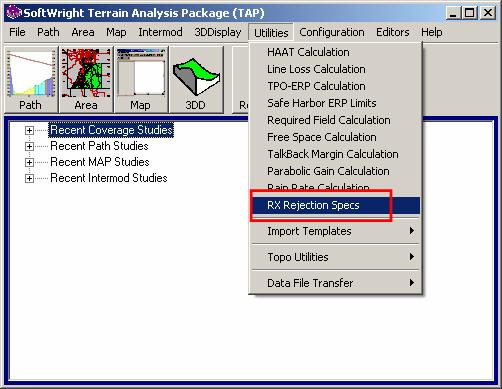
You can edit Receiver Rejection templates from the “Utilities” menu in TAP by clicking “RX Rejection Specs”
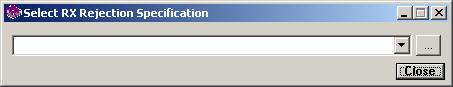
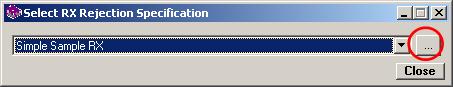
A form will be displayed to select, edit, or create the RX Rejection Template you want to use:
Specification with one channel value
Back to top
Next
Section
For example, suppose you want to create a template for a simple study that defines the RX rejection specification (a Desired to Undesired, or D/U) ratio for a single Undesired (potential interfering) channel.
Consider a desired signal with a 6MHz channel width (such as a television channel, and a potential interferer (the U channel) as a first adjacent channel with a required D/U of minus 33dB (meaning that the undesired signal must be no greater than 33dB higher than the desired signal, or conversely, the desired signal must be no lower than 33dB below the undesired signal).
This type of simplified template could be used if the Adjacent Channel Interference study you want to run includes only a single undesired signal, or if multiple undesired signals all fall into the same frequency offset from the desired signal. The channel offset used for the template would be selected based on the known frequency of the undesired signal(s).
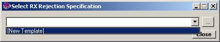
To create a new template, select the [New Template] option from the pulldown list:
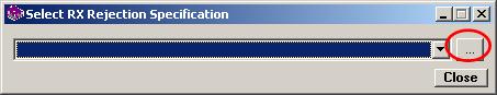
Click the Browse button (“…”) to open the template editor.
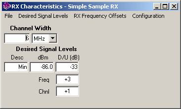
The RX Characteristics template editor is displayed:
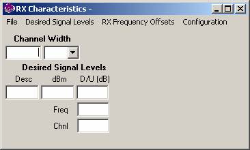
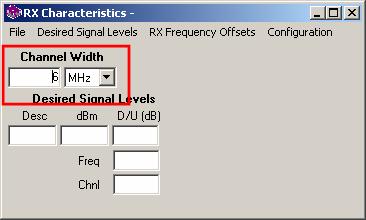
Enter the channel width for this RX specification. For this example, the channel width is 6MHz.
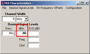
Enter a description for the minimum receiver input level for service. For this example, enter “Min”. (Note that you can also enter multiple input levels for more complicated RX specifications. These other levels might use descriptions such as “Weak”, “Moderate”, “Strong”, etc., to describe the signal level.)
Enter the receiver input value (in dBm) for the minimum required input. For this example, enter – 86dBm
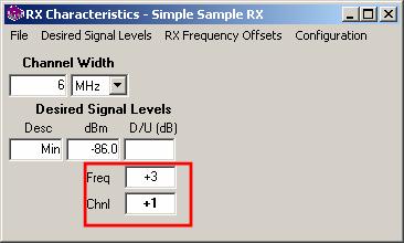
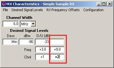
Enter the channel offset you want to include for this receiver. In this example we are looking only for undesired first adjacent, so enter a channel offset of one. When you enter the channel offset, the corresponding frequency offset is also displayed. The assumption is that the Desired signal frequency in the Area Coverage Task (the TX Frequency in the Fixed Facility database record used for the D study) is the center frequency of the channel. Therefore the first adjacent channel starts at 3MHz (half of the channel width) above the D frequency. (You can also enter multiple channel offsets, such as ±3 for third adjacent, etc.)
Enter the required Desired to Undesired (D/U) ratio in dB for this channel offset. For this example, the value is –33dB.
Note that all values in this example are for demonstration purposes only. You should determine appropriate settings for your application.
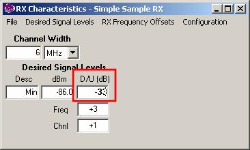
This template now defines the simple RX Rejection specification for this example – any undesired signal within ±6MHz of the desired frequency must result in a received power level no more than 33dB above the desired signal received at any given location. (The negative D/U value means that the U signal can exceed the D signal, but by no more than the specified value.)
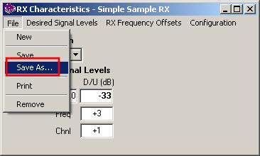
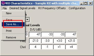
To save the template, click the File menu and click “Save As…”
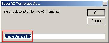
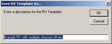
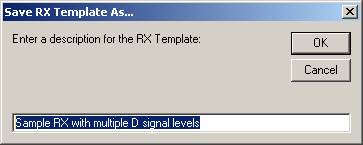
Enter a name for the template that you can recognize later when you want to select this RX specification:
That specification can now be used in an Adjacent Channel Interference study.
Specification with multiple
channel values
Back
to top
Next
Section
In many cases, the receiver specifications will include multiple channel offset values to evaluate multiple undesired signals of various frequencies.
For example, suppose you wanted to include the fourth adjacent channel on the simple template created above.
Once again use the TAP “Utilities” menu and select “RX Rejection Specs” to open the selection form. Be sure the template you just created is shown in the pulldown list and click the Browse (“…”) button:
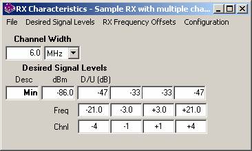
The RX Characteristics editor is opened on the template:
Instead of editing this template for this example, click the File menu and select “Save As…”
Enter a new name for the new template to be created “Sample RX with multiple channel offsets”:
To add a new channel offset, click the “RX Frequency Offsets” menu and click “Add Offset”
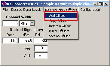
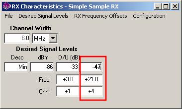
A new column is added for the Channel offset value, the Frequency offset (computed from the channel), and the associated D/U value for that offset:
The default channel offset for the added offset is the next incremental channel.
For this example, suppose you are concerned about the 4th adjacent channel (N+4) with a required D/U ratio of -47dB. You can make the change in the offset and D/U values.
Note that all values in this example are for demonstration purposes only. You should determine appropriate settings for your application.
If the channel offset D/U values are symmetrical (the D/U value for N–1 is the same as for N+1) you can use the “Mirror Offsets” function in the RX Frequency Offsets menu.
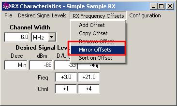
The Mirror function will create the complementary offset entries and assume the same D/U values, creating a mirror image of the offset information you have entered. Naturally, if the receiver specifications are not symmetrical (as with some measured values) you will need to edit the D/U values after using the Mirror function.
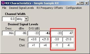
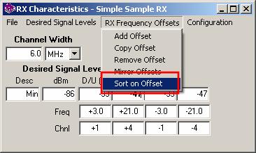
The “RX Frequency Offsets” menu and the “Sort on Offset” item can be used to manually sort the channel offsets in ascending order:
The channel offsets are automatically sorted when the template is saved:
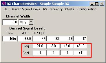
As in this example the adjacent channels may not be contiguous in all cases. (In this hypothetical example, there is no concern or no requirement about second and third adjacent channels).
With non-contiguous channels, the channel width is used to limit the Undesired signal frequencies that would be considered in the interference study. In this case, only potential interferers between 3 and 9MHz above the Desired frequency (the first adjacent channel) and between 12 and 18MHz (the fourth adjacent) would be considered. An attempt to set up a study which included other Undesired frequencies would generate a warning message.
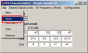
Save the template with the File-Save menu.
Specification with multiple
desired signal levels
Back
to top
Next Section
You can specify multiple levels for the Desired signal. This is useful if you want to consider that the D/U requirement may vary with a receiver as a function of the Desired signal strength at a given location.
For example, in addition to the specification for the minimum value of the desired signal suppose you wanted to include Weak, Moderate, and Strong signals, with a receiver power input level (in dBm) for each level.
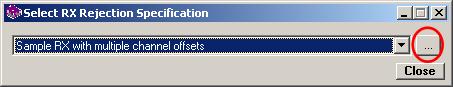
Once again use the TAP “Utilities” menu and select “RX Rejection Specs” to open the selection form. Be sure the “Sample RX with multiple channel offsets” template you just created is shown in the pulldown list and click the Browse (“…”) button:
The RX Characteristics editor is opened on the template:
Instead of editing this template for this example, click the File menu and select “Save As…”
Enter a new name for the new template to be created “Sample RX with multiple D signal levels”:
To add a new Desired Signal Level, click the Desired Signal Level menu and click “Add D Level”
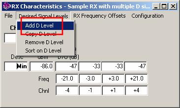
A new row is added for the Description, the receiver input power level (in dBm) and a D/U value for each channel offset that has been defined.
Then you can enter the description, input power level in dBm, and the D/U ratio for each offset.
For example you could add levels for Weak, Moderate, and Strong Desired signal levels if you have receiver specifications that correspond to those levels.
Note that all values in this example are for demonstration purposes only. You should determine appropriate settings for your application.
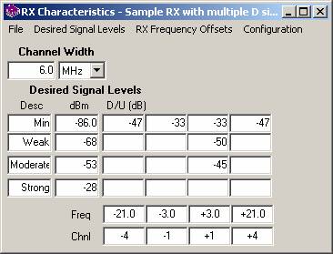
Two hypothetical values are shown in the D/U values for Weak and Moderate signals for the discussion in the following paragraph. Naturally the blank D/U levels would need to be filled in with the appropriate values from the receiver specifications, measured data, etc.
The D/U ratio applied is a step-function based on the Desired signal level. For example, in the hypothetical case above, a Desired signal between -68dBm and -53dBm is considered “Weak”, so a first adjacent Undesired signal would be required to provide at least -50dB isolation for the Desired signal to be usable. This -50dB criterion would apply to a Desired signal anywhere in the “Weak” range. A Desired signal of -53.1dBm (at the “high” end of the “Weak” range would require 50dB first adjacent isolation. A nearby “Moderate” Desired location with -52.9dBm would require only -45dB isolation.
Adjacent Channel Interference
study setup
Back to top
Next
Section
The Adjacent Channel Interference function is launched from the TAP “Area” menu by clicking “Adjacent Channel Interference”
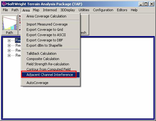
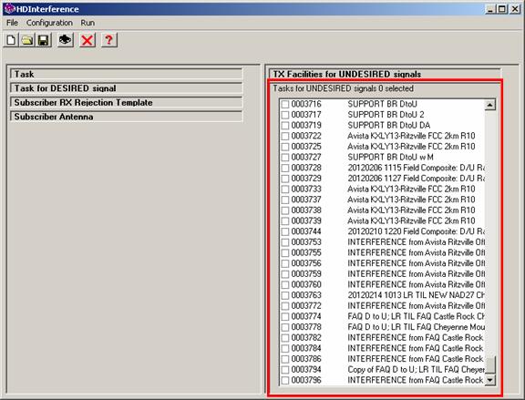
The HDInterference form is displayed:
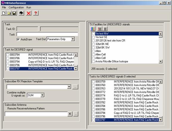
Setting up an Adjacent Channel Interference study with this form requires you to specify several parameters:
· Subscriber Antenna (optional)
· TX Facilities for Undesired signals
AND/OR
· Area coverage Tasks for Undesired signals
Click the New button to create a new Task. Setting up the Task information (creating a new Task, opening an existing Task, the Task description, “locked” Tasks, etc., are discussed in the HDCoverage article. Be sure you enter a description that will be useful to you later when you want to open this Task again, plot the results in HDMapper, etc.

The “Text Out” selection can be set to “Details” in the pulldown list to create a text file showing the specifics at every point in the study, showing the Desired and Undesired signal information.
The TAP Area Coverage study representing the Desired signal is selected by clicking the checkbox in the “Task for DESIRED signal” section.
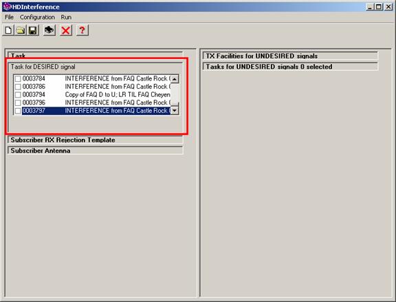
Exactly one Task must be selected. If you select a second Task, the first Task selected will be un-checked. If you try to save the study without selecting a Desired Task, a warning message will be displayed.
Only Tile or Target Point studies can be used in this function. Radial studies and contour studies are not supported for the interference calculations. The grid of locations defined in the Tile study, or the arbitrary locations defined in the Target Point study are used to define the locations for the field strength calculations for the Undesired signals.
The Desired Task must be previously setup in HDCoverage. This can be a Task that has been setup and run before, or it can be a Task that you have just created and has not been run yet. If the Desired Task has not been run, it will be run automatically when you run the study from the HDInterference form.
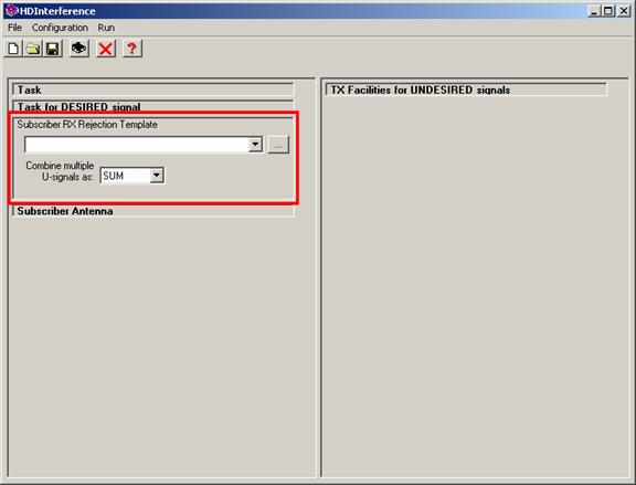
You must select the Receiver Rejection Specification template to be used in the study. You can select an existing Template from the pulldown list, or you can use the Browse button (“…”) to open the template editor to view or modify an existing template, or to create a new template.
You can also select how you want multiple Undesired signals to be combined in the interference calculation. If there are multiple Undesired signals, the individual powers can be combined by simple addition (“SUM”) or by the Root-Sum-Squared (“RSS”). (Naturally, the powers are combined by either method after converting from dBm to Watts, then the combined total is converted back to dBm for other calculations, such as the D/U ratio.)
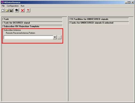
You can also include a desired signal receiver antenna pattern to be used at each of the remote locations for the D/U study.
This feature enables you to model the following scenario. The receiver for the Desired signal at each remote location is assumed to have a directional antenna with the major lobe aimed at the Desired signal transmitter. The gain and elevation of the antenna are set as usual in the "Mobile Facility" in the HDCoverage program when the study is setup. The antenna pattern is used in this Composite function for a D/U study to model the isolation provided by the directionality of the remote antenna at each location. Since the remote antenna is assumed to be correctly oriented (azimuth and elevation angle) to the desired signal transmitter, the value of the desired signal will be unaffected. However, in the majority of instances where the direction from the remote location to the Undesired signal source will be off the major lobe of the antenna, the isolation provided by the antenna pattern can be included in the D/U ratio calculation.
To add an antenna pattern to use at the remote locations, click the lookup button ("...") for the Remote Receiver Antenna Pattern. Then use the normal TAP Antenna Lookup function to find the remote antenna you want to use. To remove the antenna pattern information from the interference study, click the “X” button next to the antenna description.
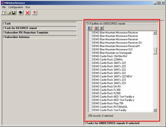
You have two options for defining the Undesired signal sources for the interference study. You can use either method, or combine some from each method.
First, you can select a Fixed Facility record representing the source of an Undesired signal. The Fixed Facility record must be previously entered into the Fixed Facility database in TAP.
When the interference study is run, TAP will automatically create a new Area Coverage Task using the coverage parameters (Tile area, topo data, propagation model, etc.) for the Desired study, but substituting the Fixed Facility parameters selected in this section. If you select multiple “TX Facilities for Undesired signals” in this section, then one Task will be created for each facility selected. The Tasks will be run when the interference study is started. After the Desired Task has been run (if needed) and then the new Tasks for Undesired signals have been run (if any facilities are selected in this section) the results of the Desired and Undesired signals are analyzed in the interference study.
Note that after you run the Interference study, if you open the study again you will see that the Fixed Facilities you checked before running the study are no longer checked, but the Area Coverage Tasks that were created using those facilities will be included in the list of “Tasks for UNDESIRED signals” after the study has been run.
In addition to, or instead of, selecting Fixed Facilities to be used to create Area Coverage studies for the Undesired signals in the interference study, you can select other TAP Tasks to use for the Undesired signals.
Select the Task(s) you want to use for the Undesired signal sources by checking the box next to the Task ID and description in the list.
If the Task(s) you select have already been run, those computed results will be used in the interference study. If they are Tasks that have been setup in HDCoverage but have not yet been run, they will be executed when the interference study is started.
The “Tasks for UNDESIRED signals” must exactly match the coverage area of the “Task for DESIRED signal.” For Tile studies, the area and grid increments (or “steps”) must match. For Target Point studies, the coordinates of each point must match points in the Desired Task. This requirement is to ensure that the interference calculations are done with the Desired and Undesired field strength computed at exactly the same locations.
Before the interference study can be saved and run, several validation checks are made to ensure all the necessary parameters have been correctly specified.
· You must have created a New Task or opened a previously created Task (one that is not locked). You must enter a Task Description.
· You must select exactly one “Task for DESIRED signal” and the Task must be a Tile or Target Point study.
· You must select a “Subscriber Rejection Template”
· You must select one or more sources for the Undesired signals, either by selecting from the Fixed Facility list, or from the Task list.
· The transmitter frequency of each Fixed Facility or each Task selected for Undesired signals must be included in the Receiver Rejection Template. In other words, if the Receiver Rejection Template only includes the first adjacent channel, and the transmitter frequency of a Fixed Facility or a Task is in the range of the third adjacent channel (and not found in the Receiver Rejection Template) the interference study cannot be saved or run.
· The Coverage area of any Tasks selected for the Undesired signals must exactly match the Coverage area of the Desired signal Task, location for location, based on the coordinates (of the Tile area or the Target points).
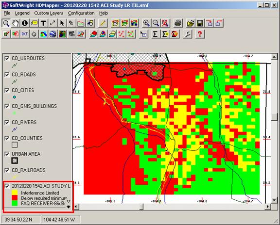
When the interference study is computed, the results can be displayed in HDMapper. The default settings show the computed values as:
· Green – Desired signal service areas (above the minimum required power in the Receiver Rejection template)
· Red – Desired signal is below the minimum required signal
· Yellow – Interference areas, where the Desired power is above the minimum but the Undesired signal(s) exceed the required D/U ratio.
If you selected “Details” for the “Text Output” in the interference study setup you can examine the detailed interference calculations in the text file Txxxxxxx.TXT, located in the WORK folder where TAP is installed.
Interference Calculation Back to top
The interference calculations can be considered as several different levels of complexity:
In this case, exactly one Undesired signal is considered relative to the Desired signal. In this case, the required D/U isolation (based on the Desired signal level and Undesired channel separation from the Receiver Rejection Specifications described above) is added to the computed Undesired signal level. If the Desired signal receiver specification for the study includes a directional antenna pattern, the antenna is assumed to be correctly aligned for maximum gain toward the Desired source. The Undesired signal is adjusted for the antenna off-axis gain for the azimuth and elevation angle from the receiver location to the Undesired source.
In this case, the criterion is:
D > (U + D/U)
Where
D is the Desired signal level
U is the Undesired signal level (adjusted for off-axis antenna gain)
D/U is the appropriate isolation based on D signal strength and U adjacency
In a more complicated scenario, there may be multiple Undesired signals. If all of the U signals being considered require the same isolation value (the D/U value discussed above), then the U value is the cumulative power of the separate U signals. Naturally, the powers (in mW) are added, NOT the dBm values. Each Undesired signal is adjusted for the antenna off-axis gain for the azimuth and elevation angle from the receiver location to the particular Undesired source. The study allows a user-selectable method, either a simple summation of the powers, or a root-sum-square value (RSS) can be used.
When the cumulative power is determined, the same criterion is used as above:
D > (U + D/U)
Where
D is the Desired signal level
U is the cumulative Undesired signal level (each adjusted for off-axis antenna gain, then a sum or RSS)
D/U is the appropriate isolation based on D signal strength and U adjacency
In some cases, multiple Undesired signals with different adjacencies (and different D/U isolation values) must be considered.
Following Obregon, et. al., the multiple Undesired signal powers are combined and weighted by the D/U isolation value required for each U signal. Each Undesired signal is adjusted for the antenna off-axis gain for the azimuth and elevation angle from the receiver location to the particular Undesired source. (A Model for Aggregate Adjacent Channel Interference in TV White Space, Evanny Obregon, Lei Shi, Javier Ferrer and Jens Zander, IEEE, 2011.)
In this case, the criterion is:
D > Σ(U + D/U)n (cp. Obregon, et. al., eq. 5)
Where
D is the Desired signal level
U n is the cumulative Undesired signal level (each adjusted for off-axis antenna gain, then a sum or RSS)
D/U n is the appropriate isolation based on D signal strength and U adjacency
In other words, for each adjacency the cumulative power of all signals at that adjacency is computed (adding mW, not dBm), and the required isolation for that adjacency and that Desired signal level (determined from the Receiver Rejection Specifications) is added to that cumulative power. The summation of that value for all computed Undesired signals (power plus isolation) must not exceed the Desired signal level.
|
|
Copyright 2011 by SoftWright LLC