Fixed Facility Database Interface
Q: How does the new interface for the Fixed Facility Database work?
A: The Fixed Facility interface presents all the fields from the Fixed Facility Database in collapsible sections on the form. This makes all the data items more accessible and eliminates the earlier mechanism of buttons to “drill down” into deeper layers in the database.
This article includes basic information on the use of the Fixed Facility Interface:
Other related articles provide additional information about using the Fixed Facility Interface
This Fixed Facility interface has the following changes and enhancements from the earlier version (these functions are discussed in more detail below):
All items are presented on a single form, using the collapsible sections to save space. This eliminates the earlier requirement to click buttons on successive forms to locate values on "deeper" layers in the data.
All the items on the single form are visible by expanding and collapsing sections. This eliminates the earlier scenario of having related items on different forms. For example, before the transmitter frequency and the transmitter line loss values were on different forms. Editing both forms was necessary to change the frequency and re-compute the line loss based on the new frequency. Now both the frequency and the line loss values are visible simultaneously.
All values on the single form update immediately. This eliminates the earlier scenario where, in some cases, the record had to be saved in order to update values for use in another part of the database. For example, in some cases after changing a frequency value it was necessary to save the record before a new line loss value could be computed. Now the values are update when they are changed on the form and the new value can be used for other calculations immediately.
More items on the new form are interactive and provide automatic updating. For example, line losses depend on a number of factors: the line library file and ID selected to define the line type, the line length, and the operating frequency. With the new form, as soon as any of these factors are changed, the line loss is recomputed and updated automatically. (If any of the values are invalid or missing, this update is not possible.) Likewise the Effective Radiated Power (ERP) depends on the Transmitter Power Output (TPO), antenna gain, and several loss values. Changing any of these values causes the ERP to be recomputed.
Where appropriate, the interactive changes and automatic updating are "cascaded". For example, the ERP calculation is affected by the losses, and the line loss depends on the operating frequency. Therefore, changing the operating frequency will be reflected immediately in a new ERP value (assuming the required line information is available).
More items on the new form provide cross-checks and display alerts. For example, if a transmitter antenna center of radiation height of 100 feet is specified, and the transmitter line length is set at 75 feet, an "alert" (listed in yellow at the top of the form) is displayed, since you may want to change the values.
More items allow a "null" or "unknown" value. This enables you to create and edit a record if only some of the information is available. The blank values can be filled later when the information is known. In the earlier version, most variables in the database had to have a value, and often default values were assigned. This required that the user go back later and change the default value. The new interface makes missing or unknown information much more obvious and easy to correct.
While site coordinates are still stored in the database as latitude and longitude values (with the WGS84 datum for new records), the user interface enables you to enter, display, and edit coordinates in any of hundreds of available coordinate systems, such as UTM, State Plane, Military Grid Reference System, etc. Each record can have its own coordinate display setting. For example a record for a facility in Colorado may use UTM zone 13 coordinates, and a record in California may use a California State Plane Coordinate System display.
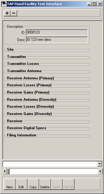
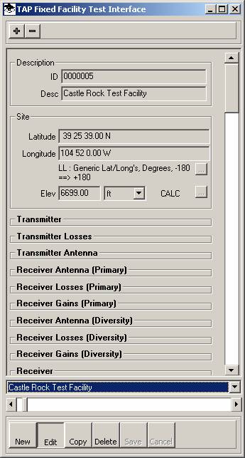
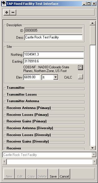
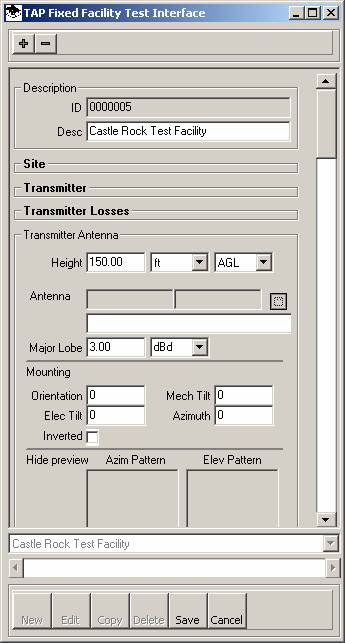
The new interface is shown below. The sections that are collapsed are shown as boldface headings. Those that are expanded show the entire contents of that section.
You can expand or collapse a section by clicking the mouse on the heading of the section.
You can expand or collapse all the sections using the “+” and “-” button on the toolbar at the top of the form.
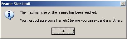
Note that it may not be possible to expand all of the sections. If the limit is reached a message will be displayed:
To create a new record, click the New button on the toolbar near the bottom of the Fixed Facility interface. After you have entered the values for the new record as described below, click the Save button to save the changes.
In some cases it may be helpful to use the Copy button on the toolbar near the bottom of the Fixed Facility interface. This will copy the current record with all the data values it contains into a new record. This can be helpful if you have several facilities at the same coordinates (for example, at different heights on the same tower). The copy function can also be used to create a duplicate record for test cases. For example, if you have a record that represents the actual existing facility at a site and you want to run a coverage study or a path profile with a higher antenna, you can use the copy function to make a duplicate of the record and change the antenna elevation. This leaves the original "As built" record intact and gives you one (or more) records you can use to try out different configurations.
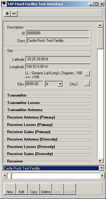
You can use the horizontal scrollbar near the bottom of the form to move through the database:
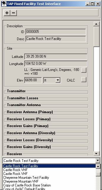
You can use the pulldown list to find a particular record in the database:
To edit the information in a record, click the Edit button near the bottom of the form:
In the Edit mode, the background of most of the fields on the form will change to white, indicating they can be edited:
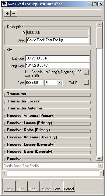
Some fields that are not directly editable (such as the program-assigned record ID) will still have a gray background.
You can click the Save button to save any changes back to the database, or you can click the Cancel button to abandon the changes and restore the original record values.
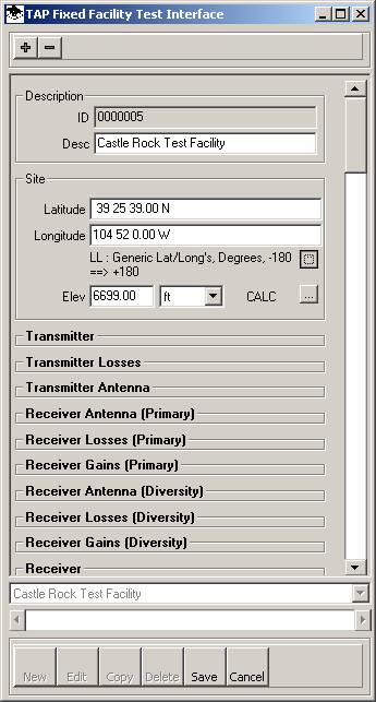
You can customize the coordinate system display mode for each record with the Lookup (“…”) button. For example, if you want to display a site using a State Plane Coordinate system (instead of the default latitude-longitude values), click the Lookup button:
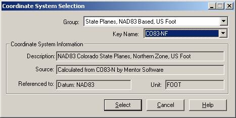
The Coordinate System Selection form will be displayed:

Select the coordinate system you want to use for this facility record:
The coordinates for this site will be displayed (and can be edited) in the selected coordinate system:
You can enter the site elevation above mean sea level (MSL) manually:
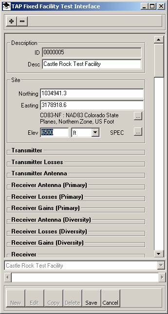
Note when you enter an elevation manually, the “SPEC” flag is set showing the elevation was specified by the user.
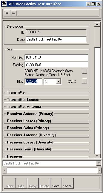
You can also use the Lookup button (“…”) to find the elevation from the available topographic elevation data:

The elevation will be updated and the “CALC” flag will be displayed to indicate the elevation is an interpolated value.
By default, the elevation will be found using the highest resolution of all available data types indexed on your TAP system. If you want to configure the Site Elevation Lookup function to use only certain data types, use the “Topo Scripts for Site Elevation” item in the TAP Configuration menu.
The Transmitter section is used to enter or edit the Transmitter Power Output (TPO) and the operating frequency of the transmitter. The Diversity Frequency is used only for Microwave calculations.
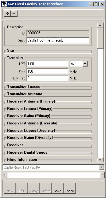
You can enter the Transmitter Power Output (TPO) in the Transmitter section, along with antenna gain in the Transmitter Antenna section and losses in the Transmitter Losses section and the program will compute the Effective Radiated Power as you make those entries or change the values. As an alternative, if you know the ERP, you can enter it near the bottom of the Transmitter Antenna section.
See the Transmitter Losses section below for information about the effect of changing the frequency value when computing transmission line losses.
The Transmitter Losses section is used for entering various loss values associated with the transmitter system for the facility.
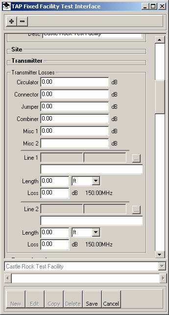
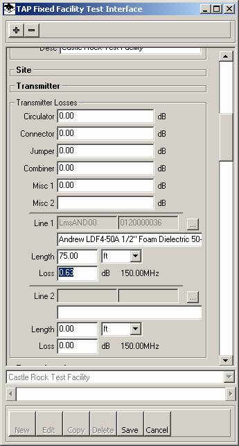
Line losses (in dB) can be entered manually:
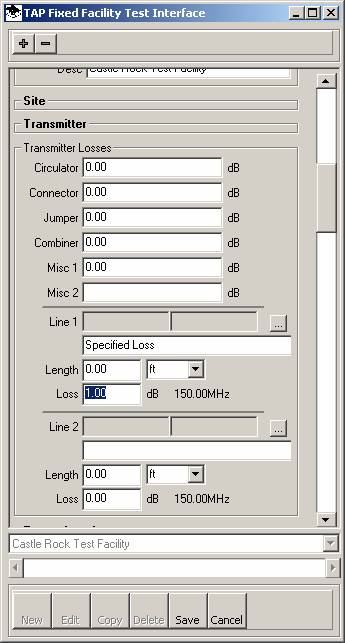
Note the loss description “Specified Loss” is added if you enter a line loss value manually.
You can also select a transmission line and specify a length for computing the line loss. To select a transmission line from one of the line libraries, click the Lookup (“…”) button:
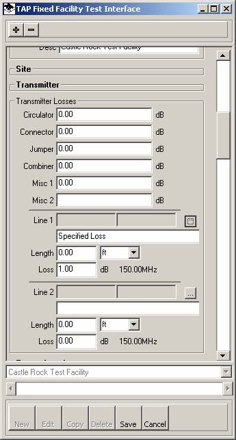
A list of transmission lines will be displayed:
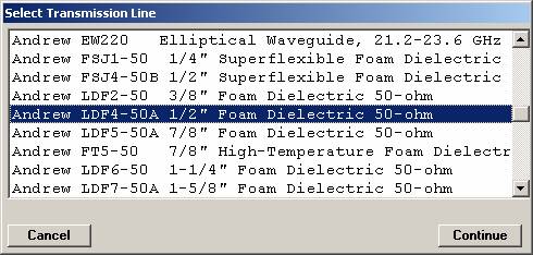
Select the line you want to use from the list and click the Continue button.
Enter the length of the transmission line and the loss value will be computed for the specified frequency:
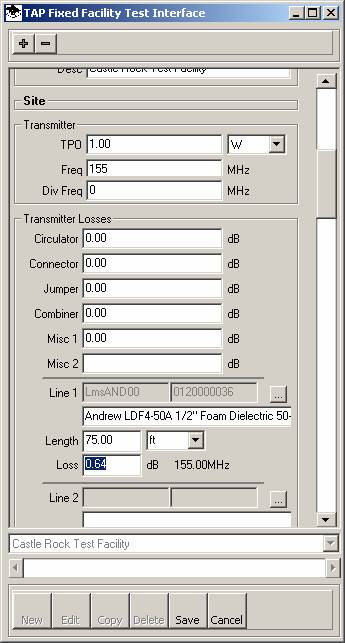
Note that if you change the TX frequency in the Transmitter section, the loss value for the selected line and length is automatically re-computed for the new frequency:
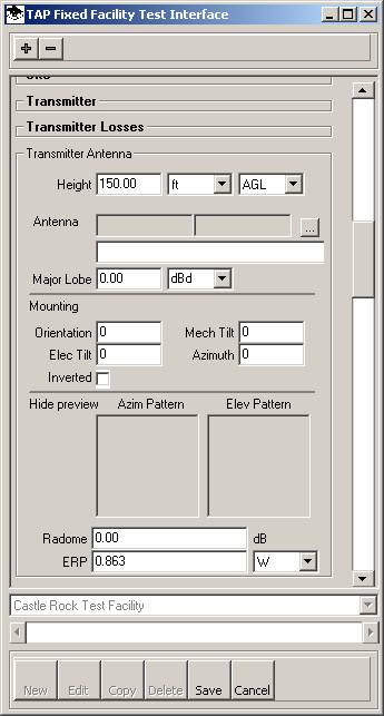
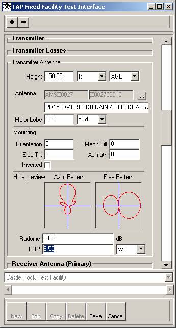
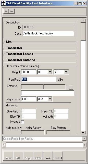
Use the Transmitter Antenna section to enter the antenna information, including the center of radiation height and mounting orientation and tilt values:
Note that if you enter a height value of the antenna, the program checks the transmission line length (if a line has been selected). If the transmission line length is less than the antenna height, a warning is displayed:
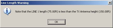
This check is performed if you change the antenna height or the transmission line length.
You can enter a gain value for the antenna manually:
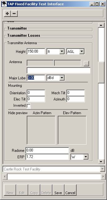
When you change the antenna gain or any of the loss values, the Effective Radiated Power (ERP) is recomputed:
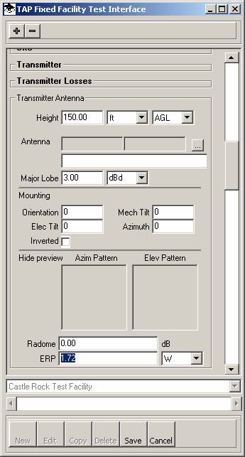
If you know the Effective Radiated Power you can enter it directly instead of letting the program compute it from the TPO and gains and losses.
You can lookup an antenna from the available libraries. Click the Lookup (“…”) button:
The Antenna Library list will be displayed. Select the antenna library you want to use:
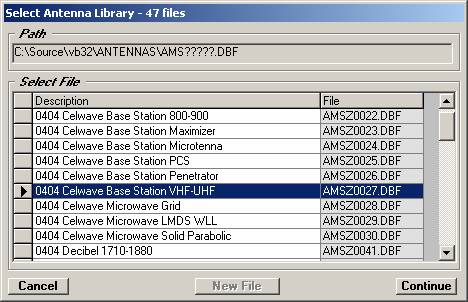
and select the desired antenna:
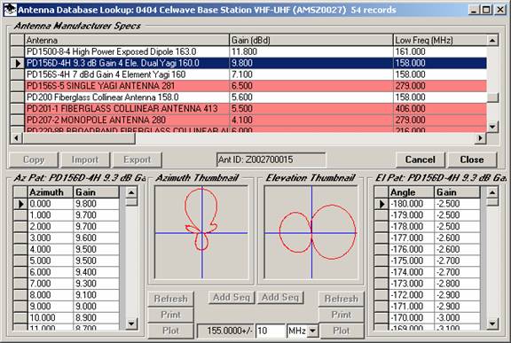
The antenna information, including a preview of the patterns, will be displayed, and the ERP will be recomputed based on the new antenna major lobe gain:
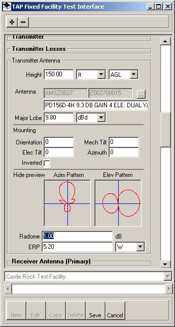
You can enter a loss value for an antenna radome, and the ERP will be recomputed to include that loss:
If you click the ‘Hide Preview” label, the antenna pattern previews will be hidden to conserve screen space and display more of the other parameters:
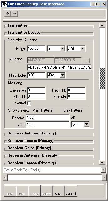
The “Show Preview” label will restore the antenna pattern previews.
The Primary Receiver parameters relate to the receiver antenna for land mobile systems. The Diversity Antenna parameters are only used in TAP for microwave space diversity antennas.
The Receiver Antenna parameters are similar to the Transmitter Antenna parameters (center of radiation height, antenna gain and pattern, etc.). However, for the receiver antennas, instead of the transmit ERP, the receiver required field value is available and can be edited directly, or it will be computed as you enter the receiver sensitivity and gains and losses, as described below.
The Receiver losses section parameters are similar to the Transmitter losses section.
The Receiver Gains section is used for additional gains associated with the receiver system, such as pre-amplifiers on microwave receiving dishes.
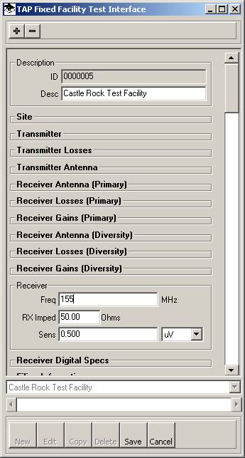
The Receiver section includes the receive frequency, operating impedance, and receiver input sensitivity.
When changes are made to the receiver gains or losses, or to the receiver input sensitivity, the receiver antenna required field is recomputed.
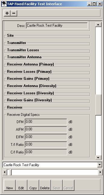
You can enter and edit the digital microwave parameters in the Receiver Digital Specs section.
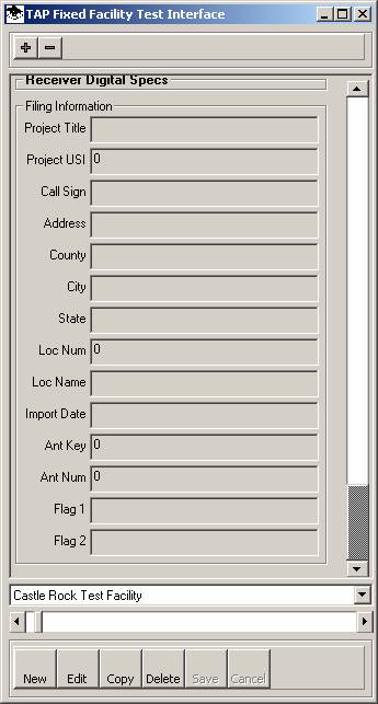
You can enter the administrative information about the facility in the Filing Information section:
|
|
Copyright 2004 by SoftWright LLC