Q: What is the "Required Field" for a fixed or mobile facility? How does this relate to the levels I set on my radial or tile coverage plots?
A: The required field information is a value you can compute to ensure that a particular receiver configuration provides adequate power to the input of the receiver.
Consider a transmitter-receiver system one part at a time:
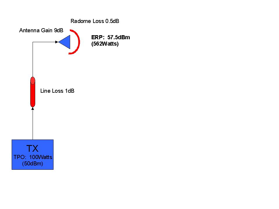
First, the transmitter system typically consists of:
The transmission system can be pictured as shown (Note that all numerical values used are for illustration only. You should determine the appropriate actual values to use for your system.):
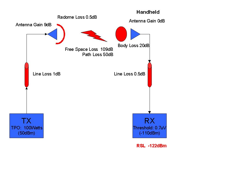
The energy radiated by the system will encounter some amount of attenuation, due to the "free-space" loss of traveling the distance to the receiver location, plus possible losses from terrain, manmade obstructions, trees, etc.

The receiver system can be viewed as a collection of its parts:

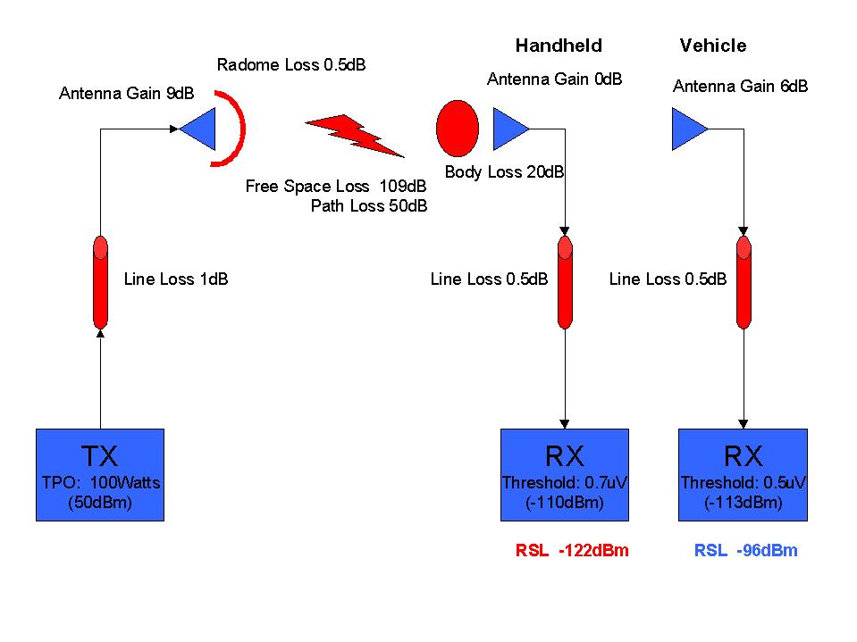
In the example above, the required receiver input (specified by the manufacturer) is 0.7uV (microvolts) or expressed as a power, -110dBm (dB relative to one milliwatt). This means that the manufacturer has designed the receiver circuitry to operate properly as long as there is at least this much signal available.
In the example, the computed Received Signal Level (RSL) is shown as -102dBm (the sum of all the gains and losses applied to the original transmitter output of 50dBm). Since the RSL is higher than the required receiver threshold the system should be expected to work.
Consider another scenario, assuming the same transmission system and path losses (the mobile receiver is in the same location), but with an additional loss included, such as body loss due to the handheld unit being carried in a jacket pocket:
Now, because of the additional loss introduced, the computed RSL is -122dBm, 12 dB BELOW the required threshold, so the receiver will not have adequate signal to operate.
In order to easily compare different receiver configurations with different receiver specifications, body losses, input impedance values, etc., TAP computes the field strength at locations. Think of it as the amount of energy at that location that is available to be received. This value is completely independent of the receiver variables. That means that once you have computed the field strength, you can evaluate it for any receiver configuration. Since the field strength calculation, typically requiring detailed topographic data, is the more time-consuming part of any study, this means you can run the study once, then evaluate it for any number of receiver configurations. (Note that the height of the receiver antenna above ground must remain essentially constant, since that will affect the geometry of the path, line of sight clearance, etc. As long as the height of each receiver configuration remains constant, this concept applies.)
The computed field strength (in dBu, short for dBuV/m, or dB above one microvolt per meter) is computed in TAP, and the Required Field utility can be used to convert that field value to the corresponding receiver input voltage or power.
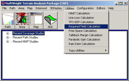
To use the Required Field utility, select it from the Utilities menu:
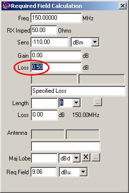
The Required Field Strength Lookup for is displayed:
(Note that you also have access to this form from other locations in the software, such as the Fixed or Mobile Facility lookup.)
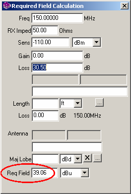
By entering the frequency and threshold values as shown, the required field strength is computed. In this case, with the 0dB antenna and 0.5dB of line loss, in order to achieve the -110dBm specified by the manufacturer, the transmitter system (less the path and free-space losses) must produce at least 9dBu of field at the location. For an area coverage study, that means that any location where there is at least 9dBu of field strength, this mobile receiver configuration will work.
If we enter an additional 30dB of loss (as represented by the body loss value above), the required field is changed to 39dBu:
The consideration of other losses (body losses, antenna mis-alignment, etc.) must always be considered. In this case, the coverage study would show that only areas with the higher field strength of 39dBu can be expected to work when the body losses are a factor, but a larger area with lower field strength down to 9dBu provide service if the body losses are avoided.
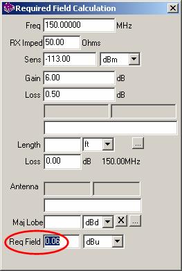
Another example would be a completely different receiver configuration, such as a vehicle-mounted mobile unit, with different gain and loss values, and even a different model of receiver, with its own specified threshold value:
You can compute the required field for that mobile unit. From the TAP Utilities menu, select Required Field:
:
Now your area coverage study can show three different field strength levels:
Remember, by carefully considering the receiver specifications, you can run a one area coverage study, then use the receiver specifications to interpret that coverage information.
After you have computed a coverage study and drawn it in HDMapper, you can set the field strength levels to show on the map:
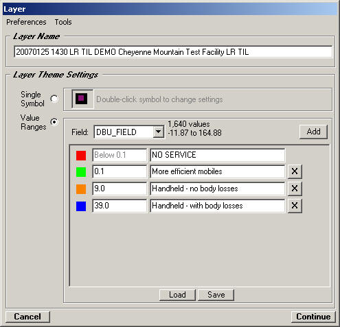
If these receiver configurations are used frequently (maybe they represent the standard mobile radios in your system), you may want to enter the specifications in the Mobile Facility database. Then you can double-click on the entries on the Layer form to retrieve the information from that database.
When the levels are entered and you plot the coverage study, the map shows the areas where each of the receiver configurations can be expected to work:
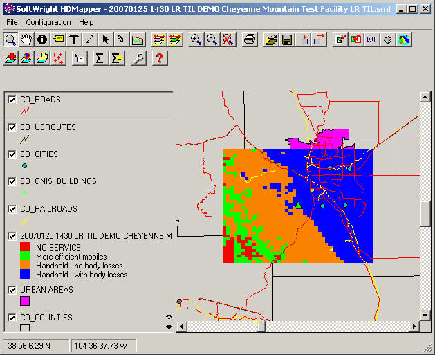
As you would expect, the case where the handheld receiver is trying to operate through significant body losses, coverage is limited to the area east of the transmitter site. (The transmitter site in this example has mountains and rugged terrain to the west.). The use of the handheld avoiding the body losses, as well as the vehicle mounted mobile system have a much longer range. Finally, you can also see, especially to the southwest, there are some areas where the signal level is so low (below the 0.1dBu level) that none of the receivers have enough signal to meet the manufacturer's specification.
|
|
Copyright 2000 by SoftWright LLC