The SoftWright Terrain Analysis Package (TAP)Ô Demo is a fully functional copy of the TAP software, subject to the geographical limits displayed when you start the demo. As you become more familiar with the TAP Demo package, you will be able to try any of the features that make TAP a powerful engineering resource.
When you run the demo the first few times, you may want to just see an overview of what TAP can do for your rf design work. That is the goal of this "Quick Tour".
The Quick Tour uses default values for several of the most common TAP functions. All you have to do is start the demo, select the operation you want to execute as described below, and click a few buttons on the screen to accept the default values. This will give you a quick idea of the type of information you can generate with the TAP software. Later, you can run the demo again and make changes to the program parameters, adjust values, etc., to learn more about the powerful flexibility of TAP. If you ever want to return to the demo default values, you can click the Configuration menu in TAP and select the option to "Reset Demo Defaults." The next time you start the TAP demo, the original defaults will be restored.
Path Profile
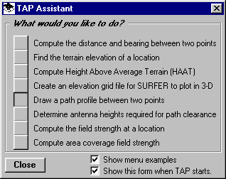
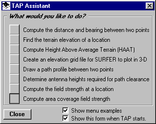
Drawing a path profile is often an important part of planning a radio facility. To draw a demo profile, click the "Draw a path profile between two points" button on the TAP Assistant form:
(If the TAP Assistant form is not displayed, select the Path item from the TAP menu, then the Path Profile option.)
The TAP Path Setup form is displayed with the default site coordinates and other information:
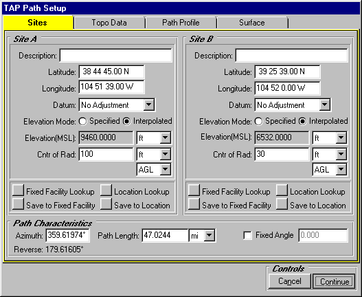
Just click the Continue button at the lower right corner. (As you can see there are several other tabs that you can explore later. For more information about the options and features for path profiles, see the TAP Training Outline.)
When you click the Continue button, the program draws a profile for the path:
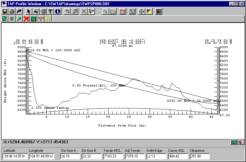
As you move the mouse along the profile, information is updated along the bottom of the form. Further explanations of this information, as well as other capabilities is described in the TAP Training Outline.
You can close the path profile by clicking the X in the upper right corner.
Antenna Elevation
In the sample profile, the path does not have line of sight between the two end points. You can use TAP to quickly determine the antenna elevation required to achieve line of sight clearance along this path.
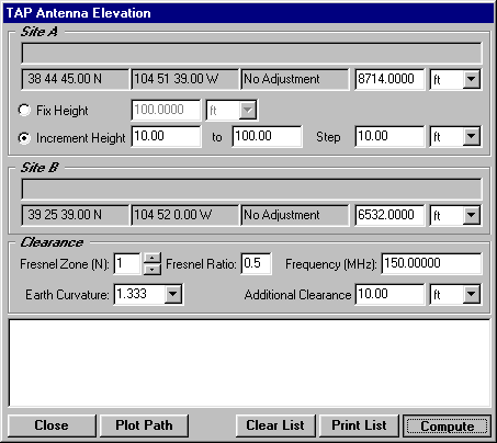
To compute the required antenna elevation, click the "Determine antenna heights required for path clearance" button on the TAP Assistant form:
(If the TAP Assistant form is not displayed, select the Path item from the TAP menu, then the Antenna Elevation option.)
The TAP Path Setup form is displayed again.

To accept the demo default values, click the Continue button.
Now, instead of drawing a profile, the TAP Antenna Elevation form is displayed.
As before, this form gives you numerous options to modify the calculation, but for now, just click the Compute button.
The window near the bottom of the form is filled with details of the calculation.
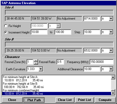
Click on the last line in the list to highlight it as shown, then click the Plot Path button.
Now the path profile is drawn with the adjusted antenna elevation to show a path with line of sight and Fresnel zone clearance:
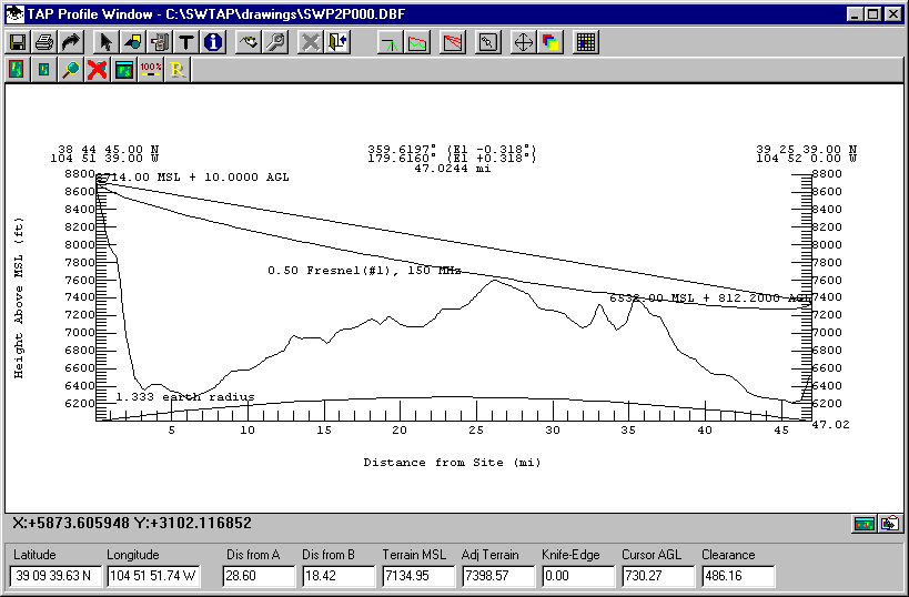
You can close the path profile by clicking the X in the upper right corner.
Area Coverage
To perform a calculation of field strength and plot a coverage map, click the "Compute area coverage field strength" button on the TAP Assistant:
(If the TAP Assistant form is not displayed, select the Coverage item from the TAP menu, then the Area Coverage option.)
This time, the TAP Area Coverage Setup form is displayed:
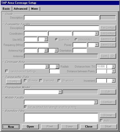
To create a new study, click the New button. The form will be filled with the default values for the coverage study:
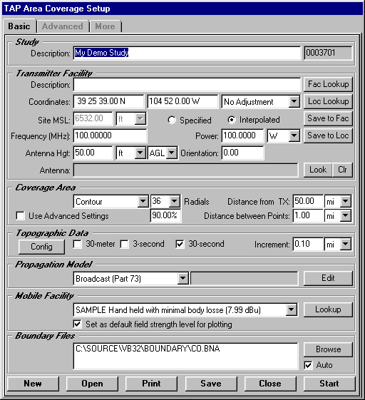
Enter a description as shown above, then click the Start button in the lower right corner to execute the study.
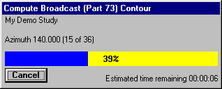
As the study is running, a progress indicator will be displayed:
When the study is completed, the Map Plot Setup form is displayed.
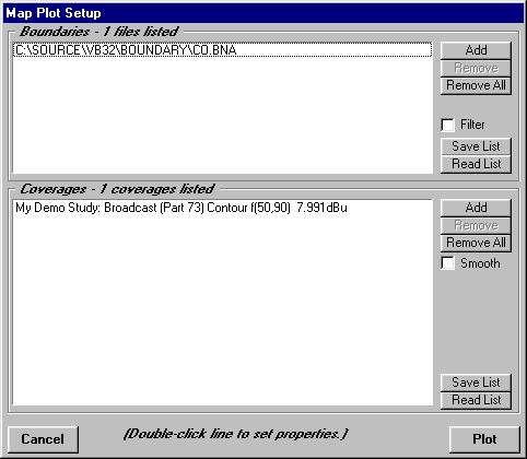
This form enables you to select what boundary files (roads, counties, etc.) you want to include, as well as the ability to draw multiple coverage studies.
To draw the coverage map, click the Plot button. The coverage contour just computed is displayed:

And there's more…
Now that you have had a brief overview of what you can do with the TAP software, you can learn much more of the details in the TAP Training Outline.
Copyright 2001 by SoftWright LLC