Computing Coverage Contour for Azimuth Range
Q: How can I compute a contour for a range of azimuths from 330 to 145?
A: The Contour calculation function in the Area Coverage program is designed to compute closed coverage contours, such as from 0 to 355 in 5 degree steps, with uniformly spaced and equal length radials.
To specify different radial parameters for computing a contour (or a radial study), you can use the Advanced tab on the Area Coverage Setup form.
Remember that under these conditions that the contour is only valid for the azimuths computed. No coverage calculations have been done on other azimuths, so no conclusions should be drawn about the signal level outside of the aperture of the computed azimuths.
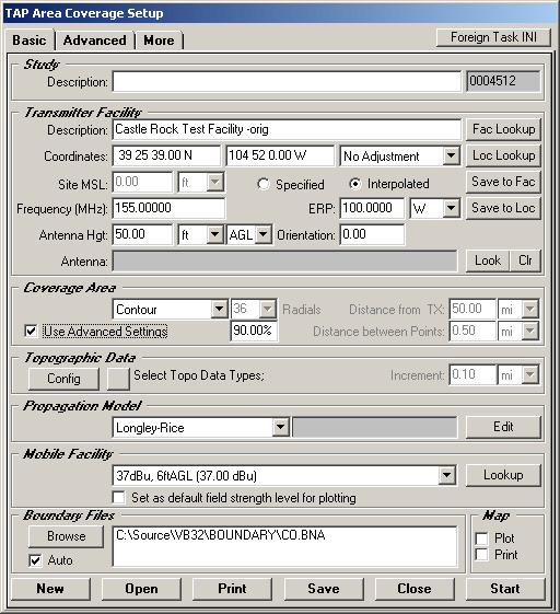
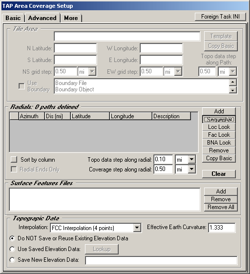
Mark the Use Advanced Settings checkbox, then click the Advanced tab:

The radials will be set in the section near the center of the form. (If any radials are already specified which you do not want to include in the study, click the first radial in the list, then hold the shift key and click the last radial in the list. Then click the Remove button to the right.)
To add sequential radials, click the Sequential button:
For this example, to define radials from 330 to 145, first specify the range from 330 to 360 degrees:

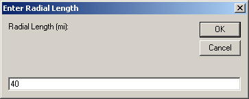
Click the Continue button and you will be prompted for the length of the radials. Enter the value you want to use for this study:
Click the OK button.
To enter the next portion of the azimuth range, click the Sequential button again:
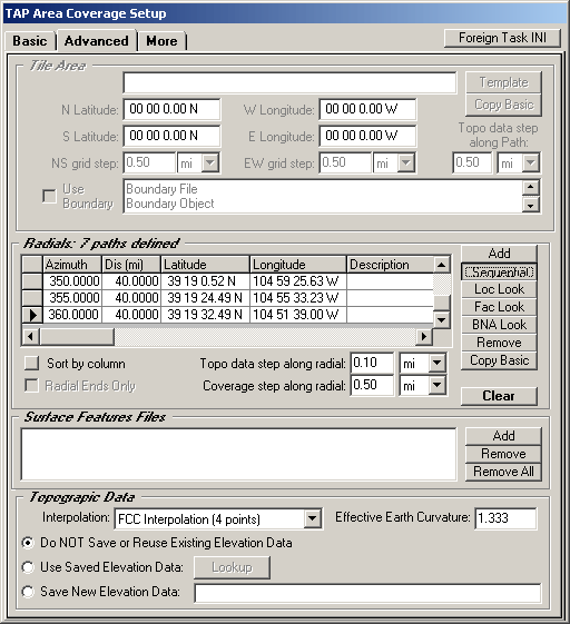
Enter the next range, from 0 to 145:

Click Continue. You will be prompted for the length for this set of radials:

Click the OK button.
To run the study, click the Basic tab and then the Start button.
When the study finishes, you can plot the coverage:
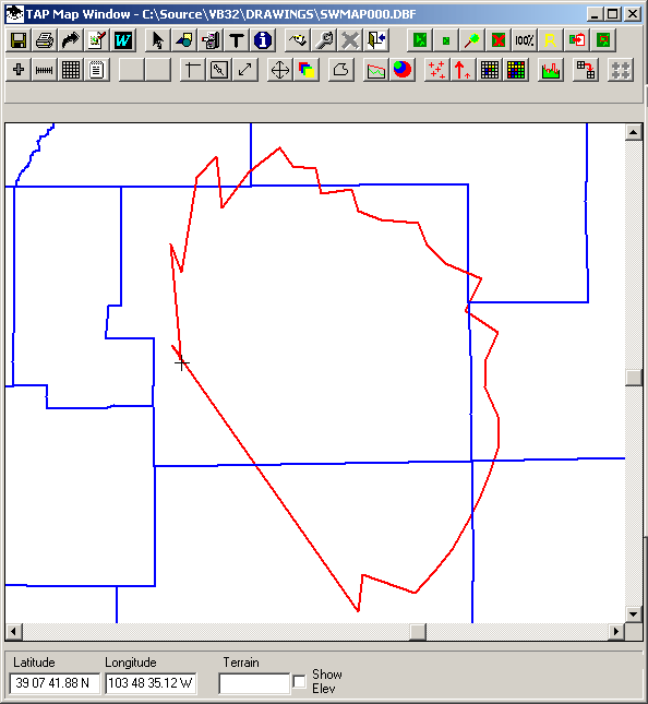
Note that the contour is computed and plotted as a continuous, closed contour. In some cases this can cause ambiguous results in the plot.
For example, suppose you used this same procedure to compute a contour from 335 to 45 degrees, a more narrow aperture of azimuths. The resulting plot would show the contour actually crossing itself northwest of the transmitter site:
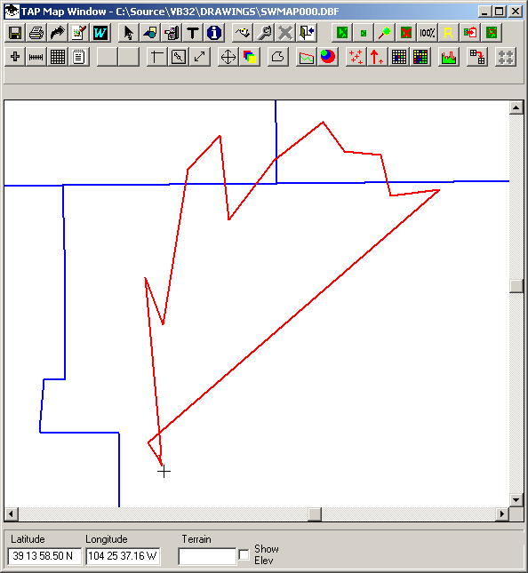
This is caused by the discontinuity in the computed results, when the point on the 45-degree azimuth is connected to the point on the 345-degree azimuth.
This problem can be avoided by adding one more azimuth before you do the calculation, to provide a point "behind" the transmitter site for drawing the contour. In this 345 to 45 degree example, another radial could be added on the 190 azimuth. The purpose of this radial is just to provide a point to ensure that the closed contour includes the transmitter site and that the contour does not cross itself.
After the ranges of azimuths (345 to 360 and 0 to 45) have been added as described above, use the Add button to include one more radial definition:
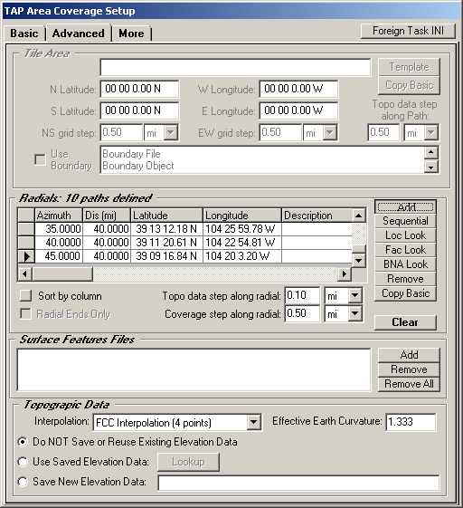
Specify an azimuth value of 190 degrees and a distance of 1 mile.
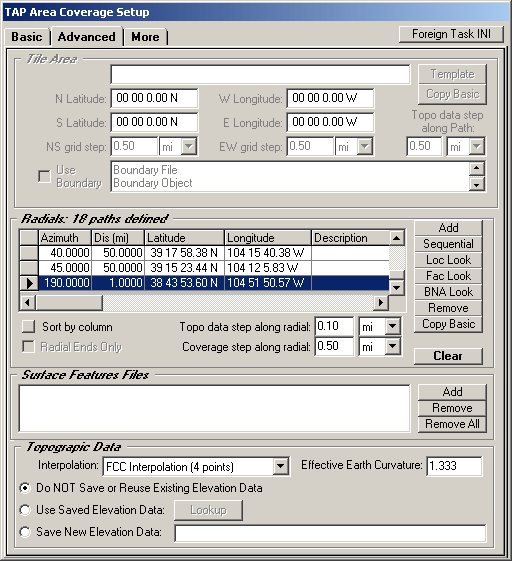
When this contour is computed and plotted, the results are clearer:
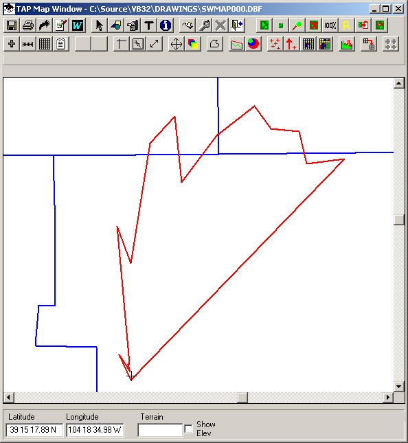
Remember that the contour shown is only valid for the azimuths computed. No coverage calculations have been done on other azimuths, so no conclusions should be drawn about the signal level outside of the aperture of the computed azimuths.
Copyright 2003 by SoftWright LLC