Fixed Angle Path Profile
Q: How can I draw a path profile showing a line of sight with a fixed antenna elevation angle?
A: With TAP6.0.2166 or later users with the Shadow Study module licensed to their TAP system can use the Shadow – Fixed Angle option in HDPath. HDCoverage can also be used to compute area shadowing with a fixed angle.
Note that all values in this example are for demonstration purposes only. You should determine appropriate settings for your application.
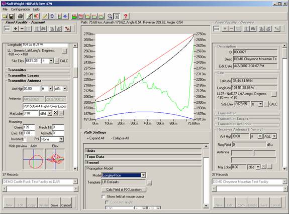
For example, suppose you have a path profile between to locations drawn in HDPath:
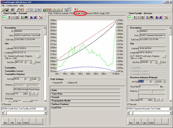
The line of sight is drawn between the antenna centers at each site, and the computed elevation angle of the path is displayed above the profile graphic.
If you want to draw a line of sight at a fixed angle, edit the Transmit Fixed Facility record and enter the desired angle in the electrical tilt box for the Transmitter Antenna section. For example, suppose you want the angle fixed at one degree (1°) tilt:
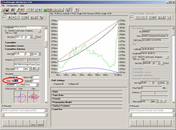
Remember that positive values are used for tilt above the horizontal, negative values for tilt below the horizontal.
Save the record if you want to write the change to the Fixed Facility database. You can also leave the record in Edit mode if you want to try different angles without saving each one.
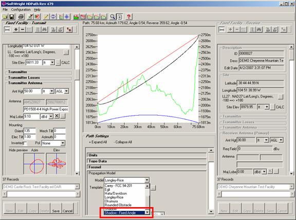
The Fixed Angle function is used when the Propagation Model selected is the Shadow – Fixed Angle selection:
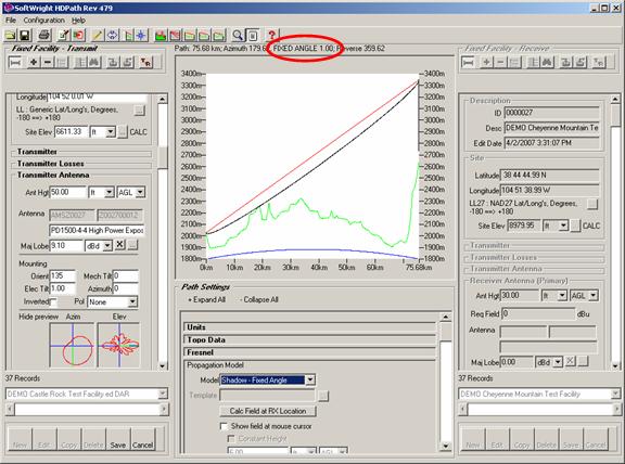
When you select the Shadow – Fixed Angle propagation model, the profile is redrawn with the fixed angle:
You can return to normal profile mode (line of sight between antenna centers) by changing to any other Propagation Model setting:
|
|
Copyright 2007 by SoftWright LLC