Q: How do I include electrical or mechanical downtilt with an antenna in TAP6?
A: You can add tilt to the antenna pattern in a library when you use the antenna with a Fixed Facility database record.
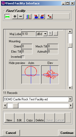
For example, suppose you are editing a record in the Fixed Facility database:

The previews indicate the general shape and orientation of the pattern information in the library. Usually (but not always), the azimuth pattern has the major lobe to the north, and the elevation pattern along the horizontal axis. This configuration will be important when you want to define how this antenna is to be installed for the specific facility, as described below.
To specify the elevation tilt (and horizontal orientation) of the antenna, click the Edit button near the bottom of the Fixed Facility interface to open the record for editing:
.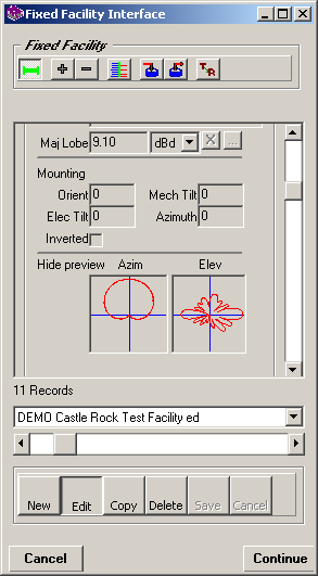
The "Mounting" section is used to specify the horizontal orientation and vertical tilt for the antenna, relative to the pattern in the library.
For example, the sample antenna selected in this exercise had the major lobe to the north. If you want the antenna installed for this facility to have the major lobe radiation to the southeast (bearing 135), you could enter an Antenna Orientation of 135. You could also enter an orientation of –225 (to rotate the antenna counter-clockwise to the same bearing). It is important to note that if the library pattern for the antenna is not to the north (bearing 0), as is the case with some manufacturers, the value you enter for the Antenna Orientation is not the desired Azimuth, but the relative rotation of the library pattern to point the major lobe in the desired direction.
Electrical beam tilt is entered in the box shown. Note that downtilt (below the horizontal) is entered as a negative value. If you enter a positive value the program will warn you that this antenna is tilted above the horizon.
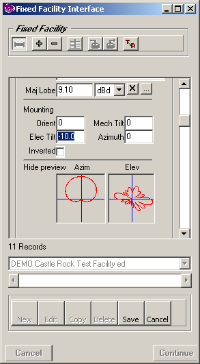
(The value of -10degrees of electrical tilt is an exaggerated value to illustrate the effect in the Elevation pattern preview shown on the form.)
Electrical beam tilt (in contrast to mechanical beam tilt, described below) adjusts the elevation pattern of the antenna by the specified amount on every azimuth. For example, if you specify an electrical beam tilt of –2.0, the elevation pattern of the antenna would be adjusted two degrees downward in every azimuth direction around the antenna.
Mechanical beam tilt is entered in the box shown.
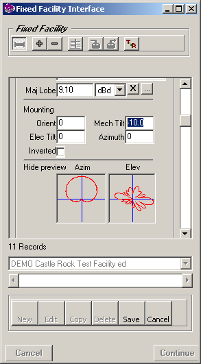
(The value of -10degrees of electrical tilt is an exaggerated value to illustrate the effect in the Elevation pattern preview shown on the form.)
Mechanical beam tilt is usually accomplished by physically tilting the antenna using brackets or shims. As a result, while the pattern is tilted down in one direction, the "backside" of the antenna (in the opposite direction) is tilted up, above the horizon, by the same amount.
Therefore, it is necessary to specify the azimuth direction of the downward tilt of the antenna in the box shown:
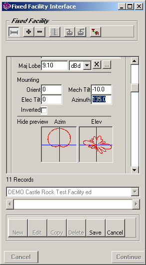
When you enter a mechanical beam tilt and the corresponding tilt azimuth, the program will use this information to compute the effect of the tilt based on each azimuth being computed for the coverage study.
The Inverted checkbox is used if the antenna is installed in an inverted position. If this box is checked, the elevation pattern values are inverted when the pattern is used in a coverage calculation.
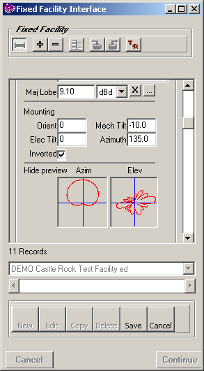
Note that the pattern is inverted after the downtilt is applied, so an inverted pattern with negative downtilt will actually be treated as an uptilt (above the horizon).
It is important to understand that the orientation and tilt information does not affect the pattern in the library. The values are applied to the pattern when used with the particular facility record. You can use the same antenna from the same library file with a different facility and have different orientation and tilt values.
It is also important to remember that the orientation and tilt values are applied relative to the pattern in the library. If the azimuth pattern in the library is not shown with the major lobe to the north (0 degrees) or if the elevation pattern is not shown with the major lobe along the horizontal axis (0 degrees), special care is needed to be sure you apply the orientation and tilt values correctly.
The electrical beam tilt values will give an estimate of the tilt on the antenna in the library, but you should consult with the antenna manufacturer for specific information about the elevation pattern with tilt added. Electrical beam tilt is usually included by the manufacturer in the construction of the antenna, feed lines, phase delay, etc. The manufactured antenna with beam tilt included may not have exactly the same pattern as the same antenna without beam tilt. Most manufacturers have pattern files for antennas with commonly used beam tilt values.
|
|
Copyright 2006 by SoftWright LLC