Excel Antenna to Generic Format
Q: How can I import the gain values from an antenna pattern in an Excel spreadsheet or ASCII file into a TAP antenna library?
A: You can edit the file to create an ASCII text file in the TAP “generic” format, then the new file can be imported with the Antenna Editor.
Note that all values in this example are for demonstration purposes only. You should determine appropriate settings for your application.
The “generic” format (essentially the same as the Planet™ format) used to import antennas into TAP contains the following information in a text-only ASCII format.
The first three header lines start with a keyword (shown in UPPER CASE below) and the corresponding values (shown in italics for purposes of illustration):
NAME antenna description
FREQUENCY fff.ff [operating frequency in MHz]
GAIN g.gg dBd [major lobe gain; can also be in dBi]
HORIZONTAL nnn [number of gain values in the horizontal pattern]
The azimuth angles and gain values follow for the number of horizontal values specified. The azimuth (starting at True north and increasing clockwise) and the gain value on each line are separated by a space. The gain value is the difference between the major lobe gain (shown in the header, on the third line) and the gain on each azimuth. In other words, the gain value for each azimuth represents how many dB down that azimuth is below the major lobe gain.
After all of the azimuth (horizontal plane) values are listed, the following line is included, showing the number of elevation (vertical plane) values are in the file:
VERTICAL nnn [number of gain values in the vertical pattern]
The elevation angles and gain values follow for the number of vertical values specified. The elevation angle of 0 (zero) represents the gain in the horizontal plane. Positive values up to +180 represent elevation angles above the horizon. Negative angles to -180 represent angles below the horizon. The angle and the gain value on each line are separated by a space. The gain value is the difference between the major lobe gain (shown in the header, on the third line) and the gain on each elevation. In other words, the gain value for each elevation represents how many dB down that elevation is below the major lobe gain.
For example, the following shows an abbreviated antenna pattern in the generic format:
NAME Simple antenna pattern
FREQUENCY 455.0
GAIN 3.00 dBd
HORIZONTAL 359
0 0.00
1 0.00
2 0.05
…
357 0.1
358 0.05
359 0.00
VERTICAL 359
180 5.00
179 4.99
178 4.90
…
2 2.8
1 2.9
0 3.0
-1 2.8
-2 2.7
-3 2.5
…
-177 4.8
-178 4.9
-179 5.0
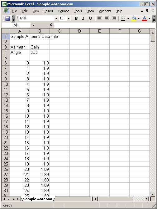
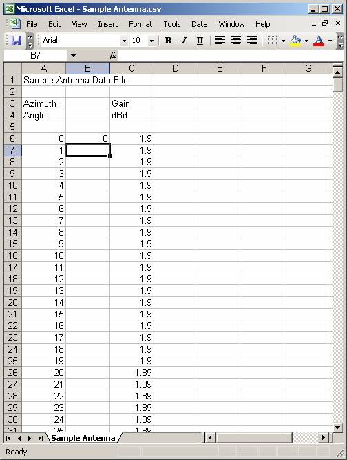
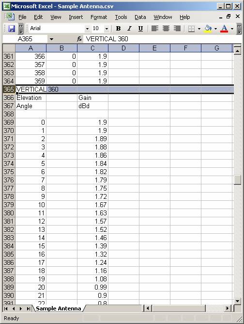
For example, suppose you have another antenna pattern in an Excel file as shown, a 1.9dBd gain antenna for a frequency of 155 MHz.
The file can be edited to add the required header lines, remove the existing unneeded lines, and change the gain values from the actual gain on each azimuth to the "dB down" value used in the generic format.
You should make a copy of the file before editing to change the format. This will preserve the original file and its format in case you have other applications that use that format. It is also important to work from a copy to avoid losing the antenna pattern information if there is a problem in the edited file.
First, insert a new column to hold the converted gain values. The column must be inserted so it is the second column in the spreadsheet. The first column must be the angle (the azimuth in the horizontal plane pattern, the elevation angle in the vertical plane pattern). The second column must be the gain value for each angle. Inserting a new column will meet this requirement.
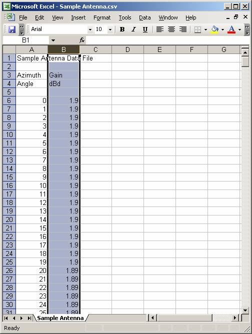
Click the column header to select the gain column:
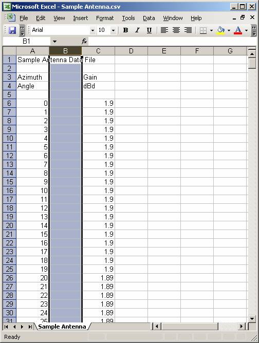
Right click the selected column, and in the popup menu, click Insert. A new, empty column will be inserted:
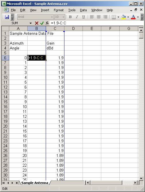
Since the gain values to be used in the new column are computed from the existing gain column, you can use an Excel "formula" to compute the values automatically. Since the generic format uses the gain value expressed as dB below the major lobe gain of the antenna, for this 1.9dBd antenna, the formula is:
1.9 – gain on each azimuth
In the first cell of the pattern values, enter the formula by typing the equal sign ("="), followed by "1.9 – C:C" The C:C represents the value in the "C" column for each row:
When you move the cursor off the row, the formula is used to compute the value to display in the cell:
Move the cursor back to the cell, and double-click the cell fill handle, the small square at the lower right corner of the cell.
l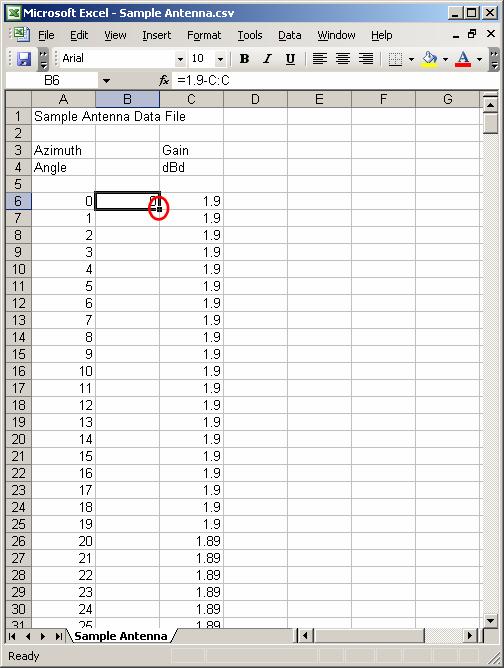
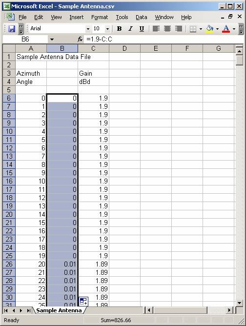
Double-clicking the fill handle will fill the rest of the cells in that column using the same formula:
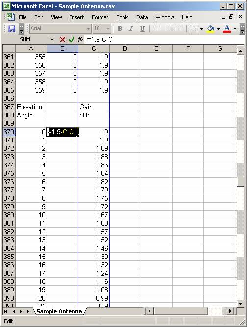
Use the same process to add the formula to the first cell in the vertical pattern: (Note the special procedure necessary if the horizontal pattern maximum is not at the 0° azimuth and the vertical elevation pattern does not have the major lobe gain as its maximum value)
Double click the fill handle for that cell to fill the column for the elevation (vertical plane) pattern.
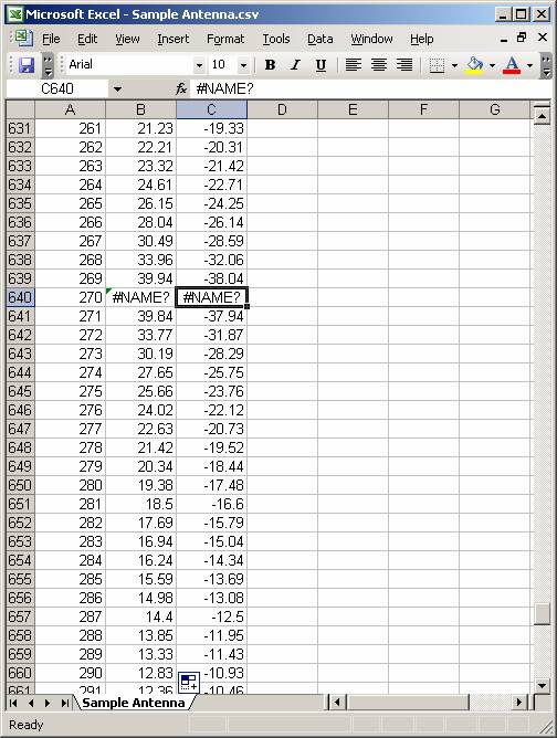
Check the values to see if the cells contain any invalid entries. For example, the computed vertical pattern of some antennas has an undefined values at ±90° (straight up or down), so the original Excel file may have an undefined value:
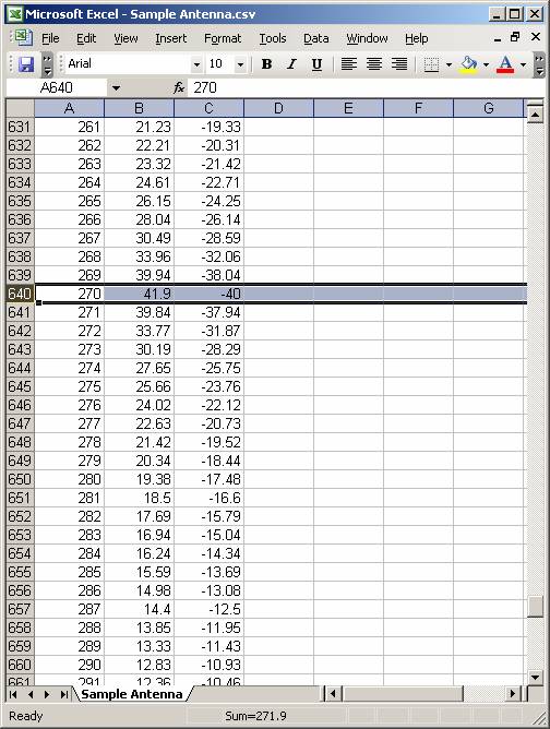
Replace the original value and the computed value will be re-calculated:
Add the header lines at the top of the file for the NAME, FREQUENCY, GAIN, and HORIZONTAL lines. Each keyword (such as NAME) is followed by a single space, then the value. There is a space between the gain value and the units (either "dBd" or "dBi") The frequency value is always in MHz:
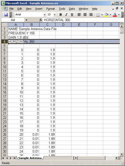
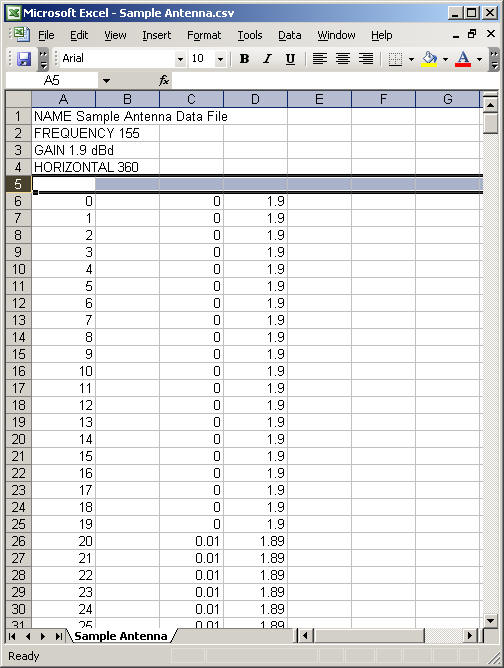
Remove any blank or unneeded original lines that were in the original file:
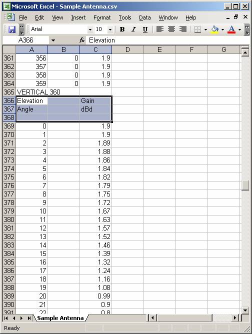
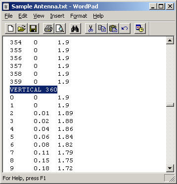
Add the VERTICAL header line at the beginning of the elevation pattern in the file:
Remove unneeded or blank lines:
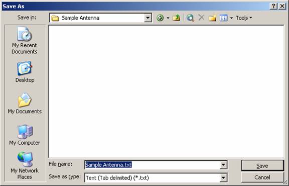
Use the File|Save menu to save the Excel file (.XLS or .CSV format). Then use the File|SaveAs menu to save a text version of the file:
Edit the text file with an ASCII editor such as NotePad or WordPad to remove the additional tabs at the end of the header lines.
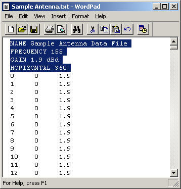
The tabs are inserted by Excel when the text file is saved, but they will cause read errors when the file is imported into TAP.
Be sure to remember to remove the tab at the end of the VERTICAL header line as well:
When the file has been saved, you can import the antenna using the Antenna Editor.
|
|
Copyright 2007 by SoftWright LLC