Creating and Editing
Transmission Lines
Q: I have the SoftWright transmission line libraries
and wish to create a line which is not currently in the TAP data
base. How can I accomplish this?
A: You will need to run the TAP Transmission Line Files
Editor to view, edit and add transmission line records. We will
illustrate this process in this tutorial.
TAP Transmission Line Data Base Overview
The TAP transmission line data base refers to a set of Microsoft
FoxPro version 2.5 tables found in the LINES\ sub-directory of
your TAP program directory. This set of files will include as
many as six different files for each library of transmission lines
depending upon the manner in which the library was created. All
line files must be located in a sub-directory named \LINES
under your TAP working directory. You can use the Transmission
Line Files Editor to view, add to or modify antenna patterns in
these files or create and edit a new set of line files.
Files such as LMSAND00.DBF that begin with the letters "LMS"
a description for each line in the library. Files such as LNDAND00.DBF
that begin with the letters "LND" contain the frequency
and attenuation values for each line used by the Transmission
Line Loss Lookup program to calculate line loss. The LMSXXXXX.CDX
and LNDXXXXX.CDX files are the associated index files for the
line data base. If you created a new line data base using the
transmission line editor, you will notice an "INF" file
such as LMSXXXXX.INF that was automatically generated for each
of the transmission line tables referenced above.
The data included in the transmission line files supplied
with TAP contain manufacturing specifications supplied by transmission
line vendors, and SoftWright does not warrant the accuracy of
the data nor the availability of line products.
Viewing Transmission Line Parameters
In this tutorial, you will view transmission line types and
their associated parameters in the Transmission Line Files Editor.
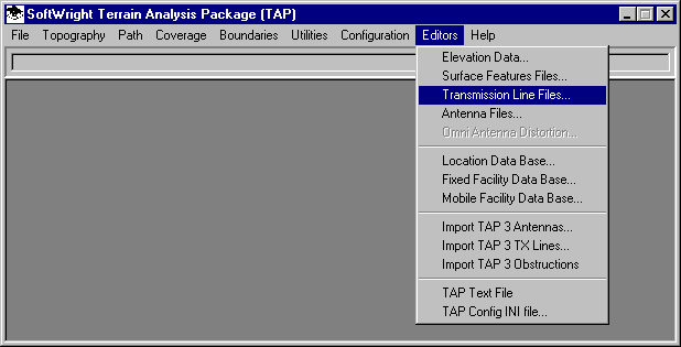
- From the main menu of TAP, use your left mouse button to
click on the Editors menu, then on the Transmission
Line Files option.
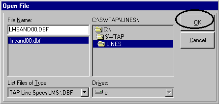
- This will display the Open File dialog. Use your
left mouse to select a line library file from the list of available
files. In this case, we select the Andrew transmission line library
and press OK.
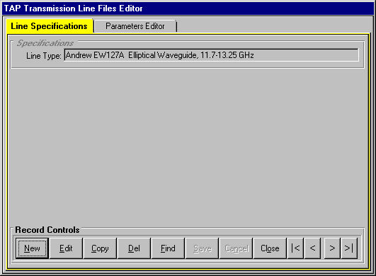
- When the TAP Transmission Line Files Editor appears,
it will display the lines in alphabetical order according to
Line Type. In our case, the "Andrew
EW127A Elliptical Waveguide, 11.7-13.25 GHz" line appears
first. We will move to a different line in the library.
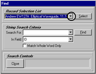
- Press the Find button at the bottom of the
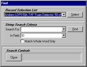
editor.
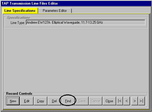
- When the Find screen appears, pull down the Record
Selection List to view a list of transmission lines.
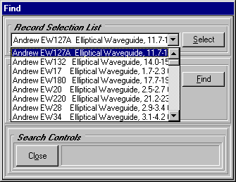
- Use your left mouse on the vertical scroll bar
to navigate to the "Andrew LDF5-50A 7/8" Foam Dielectric
50-ohm" line as we have done.
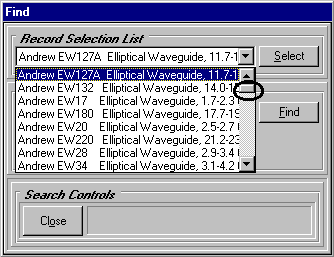
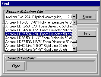
- When this line appears in the Record
Selection List press the Select button to reposition
the editor to this record.
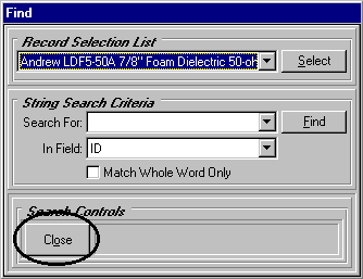
- Press Close to terminate the Find program.
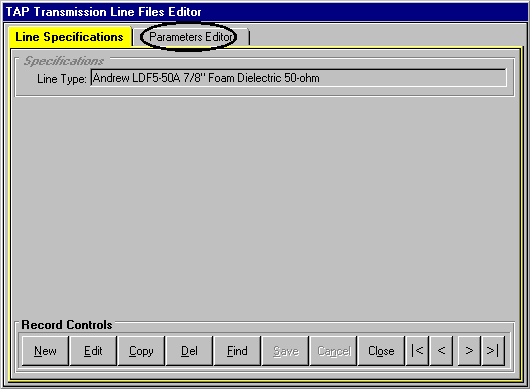
- Confirm that the Andrew LEF5-50A line is displayed
in the editor. Now select the Parameters Editor tab folder.
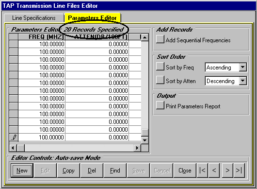
- When you move to the parameters tab, only the existing
parameters records for the CURRENT line type are displayed in
the Parameters Editor grid. If you
return to the specifications tab and move to a different line,
the parameters that are displayed the next time you view the
Parameters Editor are likely to differ.
You can make modifications to the transmission line parameters
records directly in the Parameters Editor
grid. All changes to the parameters grid cells are immediately
written to the underlying line parameters file without the need
to Save your edits. Freq
refers to frequency in MHz. Atten is
attenuation in dB/100 feet. Power is
the average power rating in kilowatts. Veloc
is the velocity of propagation percentage.
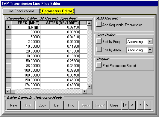
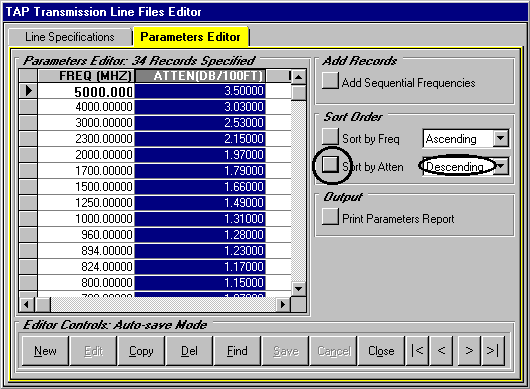
- You can use the TAP Sort Order functions to help
you analyze your data. For example, use your left mouse to pull
down the sort order list next to the Sort by Atten button in
the Sort Order frame. Press the Sort by Atten button to
sort your line parameters in ascending order by attenuation.
You can see that the 5000 MHz record has the highest attenuation
value in the file.
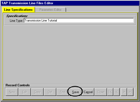
Creating a New Transmission Line
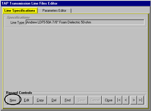
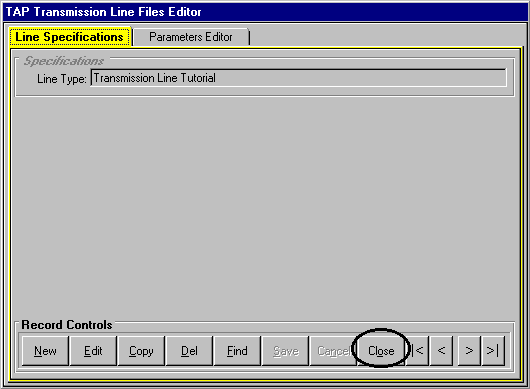
- Now press the Line Specs tab to
view the line description again. From the Line
Specifications tab folder, press the New button.
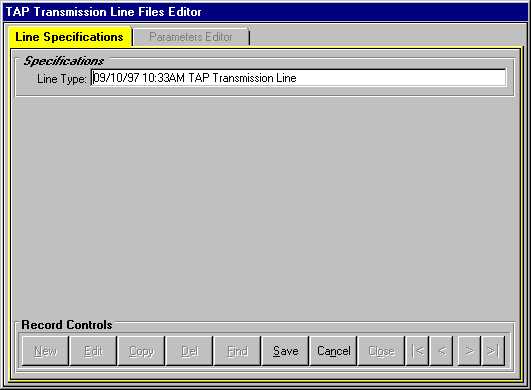
- TAP will insert a description in the Line
Type field. The white background of the text box is a
reminder that you are in "edit" mode.
- Replace the Line Type
description with "Transmission Line Tutorial"
as we have done below.
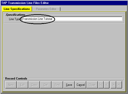
- Press the Save button to record these changes
in the line library.
- Now press the Parameters Editor tab.
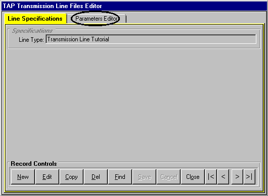
- There are currently no field records specified.
We will use the New button to add a range of records to
the grid. The values we are about to enter are purely fictional
in an attempt to simplify the data entry aspects of this tutorial.
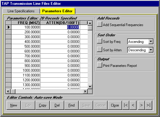
Press the New button.
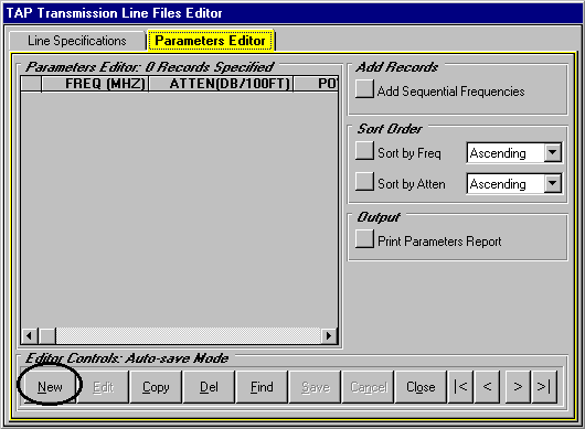
- TAP will automatically add a record to the grid
and position the record pointer to this record. A default value
of 100.0 MHz is specified for each FREQ value. We will modify
the frequency and attenuation parameters in this tutorial. In
an attempt to streamline this tutorial, we will not edit the
average power and velocity of propagation fields.
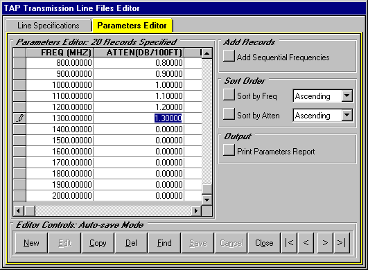
- We will add a total of 20 records to the line parameters
file for our tutorial line. Press the New button repeatedly
until the editor frame title displays "20 Records Specified"
as ours does below.
- Use your scroll bar to move to the top of this
file. Position your cursor in the frequency (FREQ)
cell of the second record as we have done.
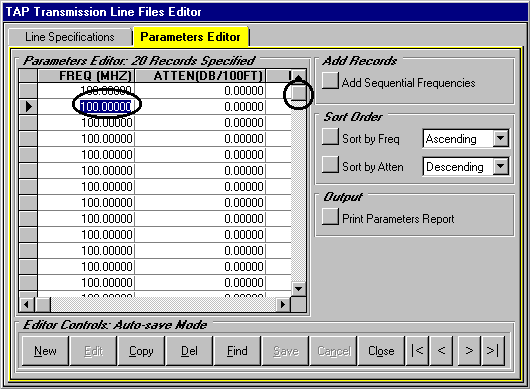
- Change the frequency field value (FREQ)
from 100 to 200 MHz.
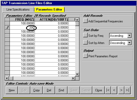
- In the same way, edit records 3 to 13 as we have
done below. In an effort to keep this tutorial as simple as possible,
you will notice that we simply increment each field value by
100 MHz.
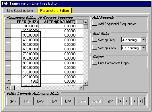
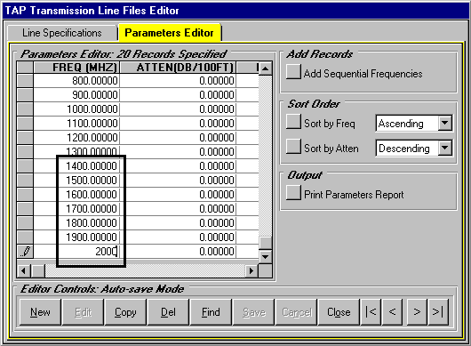
- Move the vertical scroll bar to the bottom of the
grid making the remaining records accessible. Edit the frequencies
as we have done. Verify that your frequency range is now 100
MHz to 2 GHz.
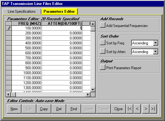
- Use the vertical scroll bar to move to the top
of the grid and position your cursor in the attenuation (ATTEN) column of the 100 MHz record.
- Change the attenuation from 0.0 to 0.1.
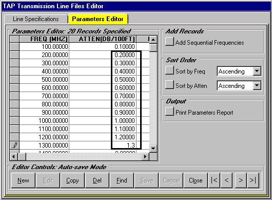
- Change the attenuation values (ATTEN)
for frequencies 200 to 1300 MHz as we have done below. In order
to simplify this tutorial, you will notice that the attenuation
value is simply the frequency multiplied by 0.001.
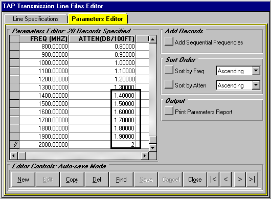
- Move the vertical scroll bar to the bottom of the
grid making the remaining records accessible.
- Beginning with the 1400 MHz record, edit the frequencies
as we have done. Verify that your attenuation range is now 0.1
to 2.0 dB/100 ft. We have finished editing the Transmission Tutorial
line parameters.
- When you are ready to continue with this tutorial
move to the Line Specifications tab.
Press the Close button. Our next step is to demonstrate
how we might use this transmission line.
Calculating Transmission Line Loss
In this part of the tutorial, you will use the TAP Transmission
Line Loss Lookup program to calculate line loss for the transmission
line we just created.
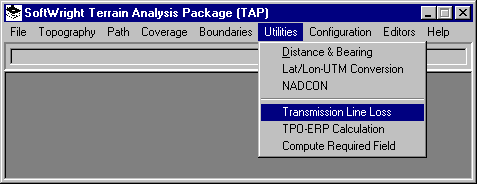
- From the main menu of TAP, use your left mouse button to
click on the Utilities menu, then on the Transmission
Line Loss option.
- This will display the Open File dialog. Use your
left mouse to select a line library file from the list of available
files. In this case, we select the Andrew transmission line library
and press OK.
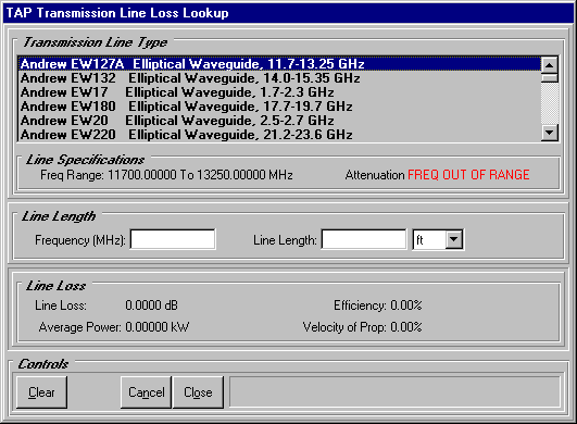
- When the TAP Transmission Line Loss screen appears,
it will display the lines in alphabetical order according to
Line Type. In our case, the "Andrew
EW127A Elliptical Waveguide, 11.7-13.25 GHz" line appears
first. We will move to a different line in the library.
- Move the vertical scroll down until the "Transmission
Line Tutorial" line is visible and select it with your left
mouse.
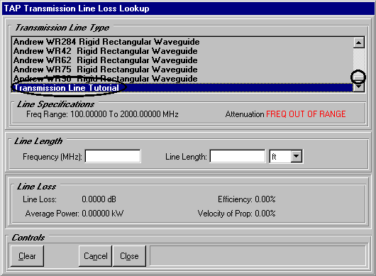
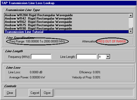
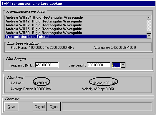
- Notice that the frequency range for this antenna
is 100 to 2000 MHz as expected. Because the Frequency
(MHz) text box does not contain a value within this range,
the Attenuation label reads "FREQ
OUT OF RANGE".
- Enter a Frequency between
100 MHz and 2 GHz such as 450 MHz. Enter a Line Length
of 50 ft. Your screen should look like ours below.
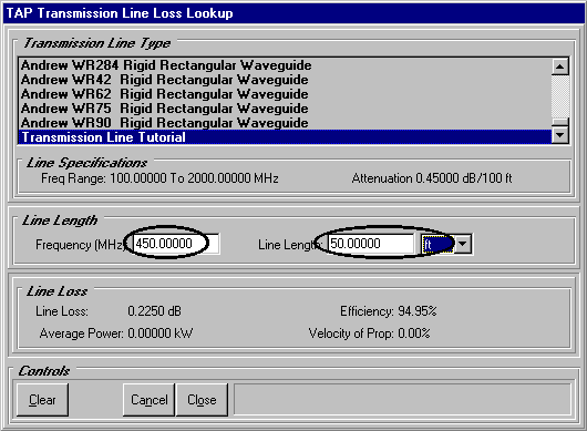
- TAP calculates a line loss of 0.45 dB for 100 ft
of tutorial transmission line. The calculated Efficiency
is 90.16%. Average Power and Velocity of Propagation are zero because
our sample line records do not contain data for these parameters.
- This concludes our tutorial. In practice, you will
obtain the manufacturer’s specifications for your transmission
line and add realistic line parameters. One final note. For convenience,
we have added our tutorial line parameters to the Andrew transmission
line library. You may wish to remove the tutorial line from the
Andrew library to avoid future confusion. In order to accomplish
this, after closing this lookup program, run the Transmission
Line Files Editor again and delete the "Transmission Line
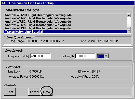
Tutorial" line. Press Close to end the lookup program.
Copyright 1999 by SoftWright LLC