Q: How are possible reflection points located along a path?
A: The method described in Engineering Considerations for Microwave Communications Systems (Lenkurt, 1970) is used.
Reflection Point Location
The reflection point locations are determined from the topographic elevation values along the path. For each point along the path, the antenna heights and path elevation at the point are used with Figures 7A and 7B from Lenkurt. The reflection point distance for that path elevation is determined for both 2/3 (Figure 7A) and 4/3 earth curvature (Figure 7B). This range of distance defines the portion of the path where a point of the specified elevation could be a reflection problem within the 2/3 to 4/3 range of possible earth curvature values.
If the distance of the path point under consideration is within that range, then the location on the path is considered a possible reflection point. In other words, for the elevation of the point at the distance of the point, there exists an effective earth curvature value between 2/3 and 4/3 that would make the point a potential reflection point. (If the distance of the point along the path is outside of the distance range determined from the 2/3 and 4/3 Lenkurt curves, the assumption is that the point is not a potential reflection point for any reasonable effective earth curvature value.)
The earth curvature value is interpolated between 2/3 and 4/3 earth based on the relative location within the computed distance range. This gives the approximate earth curvature value at which a point at that distance and that elevation would present a reflection concern.
For example, consider a path 39.9 miles long, with antennas at each end with elevation values of 3855 feet and 4809 feet. A point along the path at a distance of 9.2 miles has an elevation of 3626 feet. Based on Lenkurt's Figure 7A and 7B for that path elevation and antenna height configuration, the reflecting point distance at 2/3 earth curvature is 9.43 miles, and for 4/3 earth the distance is 7.83 miles. Since the point under consideration (at 9.2 miles) lies in that distance range, it must be considered as a potential reflecting point.
Reflected Ray Line of Sight
The reflection effects of the point are only of concern if both ends of the path have clear line of sight to the potential reflecting point. Any obstruction in the path would block the reflected ray. Therefore, the next step is to see if this line of sight exists. Two paths are considered: from the transmitting antenna to the point under consideration (at ground level), and from that point to the receiving antenna.
The line of sight from that point to each end-point antenna is checked. If either path is blocked then the ray reflecting from that point on the path will be blocked, preventing a complete reflecting path, and the point will be ignored. The line of sight is checked at the earth curvature value computed for the point as described above.
Earth Curvature Values
The location of the potential reflection point as determined from Figure 7A/B in Lenkurt indicates the possibility of a reflected ray at the point somewhere in the range of effective earth curvature values in the range from 2/3 to 4/3 earth. The line of sight for the reflecting ray can be checked for a total of four possible values of effective earth curvature:
Interpretation
Suppose the shadowing of the terrain blocks either part of the reflected ray path at an effective earth curvature of infinity (the most likely to have a clear path). Then the assumption can be made that the reflected ray at that point will not affect the received signal at the end of the path. Any consideration of earth curvature effects that would "bend" the topography upward along the path would only result in more effective blocking of the reflected ray.
At the other extreme, suppose the shadowing of the terrain allows a clear path for the reflected ray even at 2/3 earth curvature (the maximum "bending" effect considered). In this case, the potential reflecting point is of concern, since any reflected signal has the potential to reach the receiving antenna and cause interference or cancellation.
In the event that neither of the extreme conditions are met, the two shadowing evaluation studies (at 4/3 earth and at the interpolated effective curvature value) will give a relative idea of the potential severity of the reflection point.
The prediction of a reflection point does not ensure that a reflection will actually occur. Other factors, such as the topography at the point and the type of surface will also have significant effect on the actual reflection. The determination of the reflection point location assumes a level surface at the reflecting point (in order for the angle of incidence and the equal angle of reflection to result in a continuous path between the antennas). The reflection coefficient at the point will determine how much of the signal energy is reflected toward the end point antenna. Smooth surfaces (relative to the wavelength) result in the most reflection. A large lake would generally present a serious concern, while heavy vegetation would significantly reduce the likelihood of reflection. A physical inspection of possible reflection point locations is important to determine the realistic probability of actual destructive reflections along the path.
Program Operation
(This article describes the operation of the TAP4 version of Path Reflection analysis. TAP systems (Version 5.0.1056 and later) with a Maintenance Subscription date of June 30, 2005 or later, and that include the Reflection Analysis module can use HDPath to compute the possible reflection points.)
To start the Reflection Analysis function, use the TAP Path menu and select "Reflection Analysis":
The form for specifying the path end points is displayed:
Enter the site and antenna height information directly on the form, or you can use the Fixed Facility lookup or the Location lookup to retrieve the information from the TAP data bases.
Click Continue to start the reflection analysis process. The results will be displayed on a form showing each potential reflection point, and for each point:
The point with the highest potential loss value is highlighted when the form opens.
You can change the reflection coefficient of any point and the reflection effect (loss or gain) will be recomputed.
You can click the Print button to display a summary of the computed reflection analysis for all the points. The summary is written to a temporary file and opened in Notepad.
You can click Plot Profile to draw a profile of the path showing the potential reflection path (shown as the narrow red line in the profile below).
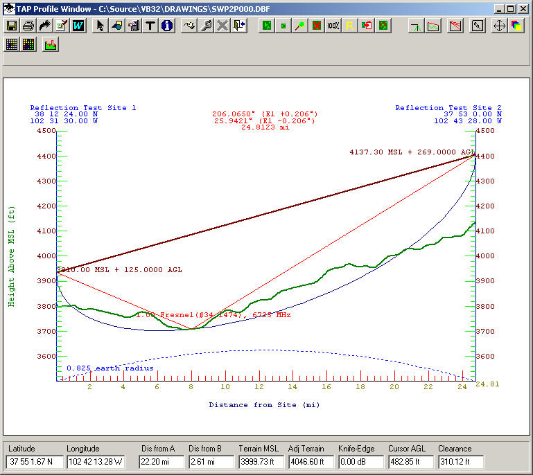
As indicated on the Reflection Point Analysis form and on the profile plot, this point would be of concern since both of the reflected rays are unobstructed.
The nature of the terrain at the reflection point should also be considered. You can use the TAP Land Use function to determine the USGS Land Use Land Cover classifications along the path.
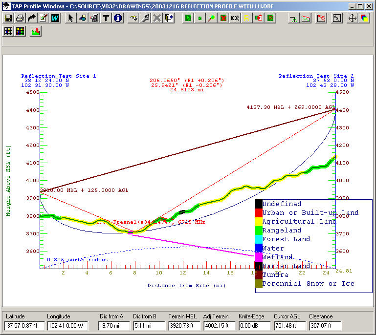
Note that "Wetland" areas are shown in the vicinity of the reflection point. This could indicate areas of a high reflection coefficient resulting in significant destructive interference. The actual nature of the terrain in the area should be determined from a recent map or a field visit.
Copyright 2000 by SoftWright LLC