HDPath Reflection Analysis
Q: How do I use HDPath™ to compute possible reflection points along a path?
A: The method described in Engineering Considerations for Microwave Communications Systems (Lenkurt, 1970) is used
TAP systems (Version 5.0.1056 and later) with a Maintenance Subscription date of June 30, 2005 or later, and that include the Reflection Analysis module can use HDPath to compute the possible reflection points.
Reflection Point Location
The reflection point locations are determined from the topographic elevation values along the path. For each point along the path, the antenna heights and path elevation at the point are used with Figures 7A and 7B from Lenkurt. The reflection point distance for that path elevation is determined for both 2/3 (Figure 7A) and 4/3 earth curvature (Figure 7B). This range of distance defines the portion of the path where a point of the specified elevation could be a reflection problem within the 2/3 to 4/3 range of possible earth curvature values.
If the distance of the path point under consideration is within that range, then the location on the path is considered a possible reflection point. In other words, for the elevation of the point at the distance of the point, an effective earth curvature value exists between 2/3 and 4/3 that would make the point a potential reflection point. (If the distance of the point along the path is outside of the distance range determined from the 2/3 and 4/3 Lenkurt curves, the assumption is that the point is not a potential reflection point for any reasonable effective earth curvature value.)
The earth curvature value is interpolated between 2/3 and 4/3 earth based on the relative location within the computed distance range. This gives the approximate earth curvature value at which a point at that distance and that elevation would present a reflection concern.
For example, consider a path 39.9 miles long, with antennas at each end with elevation values of 3855 feet and 4809 feet. A point along the path at a distance of 9.2 miles has an elevation of 3626 feet. Based on Lenkurt's Figure 7A and 7B for that path elevation and antenna height configuration, the reflecting point distance at 2/3 earth curvature is 9.43 miles, and for 4/3 earth the distance is 7.83 miles. Since the point under consideration (at 9.2 miles) lies in that distance range, it must be considered as a potential reflecting point.
Reflected Ray Line of Sight
The reflection effects of the point are only of concern if both ends of the path have clear line of sight to the potential reflecting point. Any obstruction in the path would block the reflected ray. Therefore, the next step is to see if this line of sight exists. Two paths are considered: from the transmitting antenna to the point under consideration (at ground level), and from that point to the receiving antenna.
The line of sight from that point to each end-point antenna is checked. If either path is blocked then the ray reflecting from that point on the path will be blocked, preventing a complete reflecting path and the point will be ignored. The line of sight is checked at the earth curvature value computed for the point as described above.
Earth Curvature Values
The location of the potential reflection point as determined from Figure 7A/B in Lenkurt indicates the possibility of a reflected ray at the point somewhere in the range of effective earth curvature values in the range from 2/3 to 4/3 earth. The line of sight for the reflecting ray can be checked for a total of four possible values of effective earth curvature:
- 2/3 earth: This is the case that would provide the highest amount of obstruction along the path, i.e., the most amount of effective "bending" of the topography upward, giving the highest probability that some of that topography will obstruct one or both paths of the reflected ray. Hence, this is the most "optimistic" modeling, showing the maximum likely amount of terrain shielding of the reflected rays.
- 4/3 earth: This is the upper limit of the Lenkurt modeling, often used for typical atmospheric bending.
- Infinity: This is the case with no adjustment of the topography for earth curvature (effectively a "flat earth" approach). This is the case that would provide the least amount of obstruction along the path, i.e., the highest probability that the reflected ray would indeed have a clear path and be a potential problem. This can be considered the most "pessimistic" modeling, showing the least amount of shielding of the reflected rays.
- The interpolated value, based on the range of distances determined from Lenkurt. For example, in the path described above, the reflecting point distance at 9.43 miles corresponds to an earth curvature of 2/3 (0.666), and the distance of 7.83 miles corresponds to an earth curvature of 4/3 (1.333). Interpolating linearly, 9.2 miles (the actual distance of the point under), would correspond to an earth curvature value of 1.239.
Interpretation
Suppose the shadowing of the terrain blocks either part of the reflected ray path at an effective earth curvature of infinity (the most likely to have a clear path). Then the assumption can be made that the reflected ray at that point will not affect the received signal at the end of the path. Any consideration of earth curvature effects that would "bend" the topography upward along the path would only result in more effective blocking of the reflected ray.
At the other extreme, suppose the shadowing of the terrain allows a clear path for the reflected ray even at 2/3 earth curvature (the maximum "bending" effect considered). In this case, the potential reflecting point is of concern, since any reflected signal has the potential to reach the receiving antenna and cause interference or cancellation.
In the event that neither of the extreme conditions are met, the two shadowing evaluation studies (at 4/3 earth and at the interpolated effective curvature value) will give a relative idea of the potential severity of the reflection point.
The prediction of a reflection point does not ensure that a reflection will actually occur. Other factors, such as the topography at the point and the type of surface will also have significant effect on the actual reflection. The determination of the reflection point location assumes a level surface at the reflecting point (in order for the angle of incidence and the equal angle of reflection to result in a continuous path between the antennas). The reflection coefficient at the point will determine how much of the signal energy is reflected toward the end point antenna. Smooth surfaces (relative to the wavelength) result in the most reflection. A large lake would generally present a serious concern, while heavy vegetation would significantly reduce the likelihood of reflection. A physical inspection of possible reflection point locations is important to determine the realistic probability of actual destructive reflections along the path.
Program Operation
For example, suppose you have a profile plotted in HDPath:
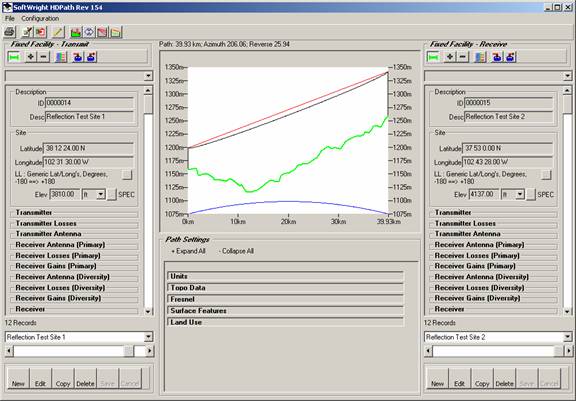
While the path has a clear line-of-sight, you can use HDPath to check for possible reflection points.
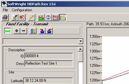
Click the Reflection Analysis button on the toolbar in the upper left portion of the HDPath form:
The Path Reflection Analysis form will be displayed with the results of the calculation:
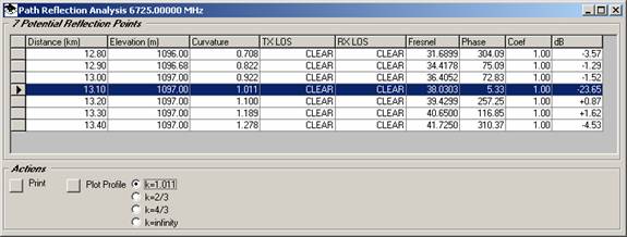
The form is displayed with the worst-case reflection point highlighted.
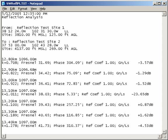
You can click the Print button to display a summary of the computed reflection analysis for all the points. The summary is written to a temporary file and opened in Notepad:
You can click the Plot button to draw the reflection paths on the profile:
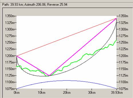
As indicated on the Reflection Point Analysis form and on the profile plot, this point would be of concern since both of the reflected rays are unobstructed.
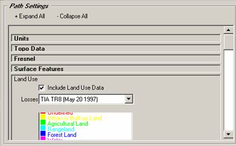
The nature of the terrain at the reflection point should also be considered. If your TAP system includes the Land Use module, you can add land use information to the profile to determine the USGS Land Use Land Cover classifications along the path.
The Land Use information is added by checking the box in the Land Use section of the form:
When you redraw the path and the reflection point information, you can see the Land Use information near the reflection point:
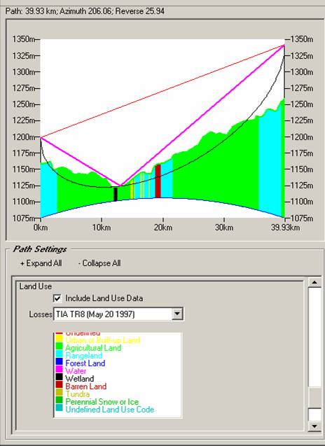
In this example, note that there is an area of “Wetland” (listed in the Land Use legend) very near the reflection point. This is another example of a actual TAP user scenario, and a field visit to the area showed that the actual area of wetland extended into the area of the reflection point and was actually cause a signal problem on the path. Move the antenna heights relocated potential reflection points away from the wetland into agricultural areas and eliminated the problem.
|
|
Copyright 2005 by SoftWright LLC