
TAP UHF/VHF Link Budget Program
OBJECTIVE: To understand the basic operation of the TAP UHF/VHF Link Budget program, including the creation of UHF/VHF facilities and the calculation of fade margin.
In this tutorial, you will select two UHF/VHF facilities and calculate a link budget analysis for the path between these two sites. We will use your TAP sample topographic data base files and choose from TAP’s list of available engineering models such as Longley-Rice in order to calculate a predicted transmission loss for the path. TAP will calculate a thermal fade margin based on the received signal level, receiver threshold, predicted transmission loss and other factors described in this tutorial.
In this tutorial, predicted transmission loss will be calculated using terrain elevation information from USGS 30 second elevation files copied to your computer during the TAP installation process. Let’s first verify that your TAP topographic data configuration is properly defined to utilize this terrain data. Use your left mouse button to click on the Configuration menu, then on the Topographic Data option.

The Elevation Data File Path form is displayed:

The data path dialog screen will appear. (Note that the screen may already contain entries for data paths as shown).

If your TAP system already has a data path entry as shown, you may still want to go through this section of the tutorial to learn how to add additional paths, such as a CD-ROM drive to the list.
For purposes of this tutorial, we assume that your TAP program was installed in the C:\SWTAP directory. If this is not the case, substitute your TAP installation path for C:\SWTAP in the instructions that follow.
If an elevation data path definition for "SW 30-SEC BINARY" terrain data on path "C:\SWTAP\DATA" does not already exist, you must create it. If it is already defined, skip over the data file path instructions that follow. Press the Add button in the upper right corner of the Elevation Data Path screen. The New Elevation Data File Path dialog will appear. By default, the File Format selection on the right side of this screen is positioned to "SW 30-SEC BINARY" which is the first entry in the list. The SoftWright 30 second binary format happens to be the correct file format for this tutorial. Double-click the C:\SWTAP\DATA directory so that your screen looks like ours below.
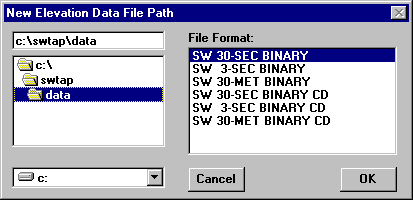
Select the OK button in order to display "C:\SWTAP\DATA\" in the data file path screen. The "Chg" option that is currently set to "NO" refers to the TAP option to pause when a data file is needed but not found in the file paths listed in this screen. When Chg is "NO", TAP will simply skip the missing data points and continue extracting elevation data.

Select OK to close the topographic configuration screen.
From the main menu of TAP, use your left mouse button to click on the Path menu, then on the UHF/VHF Link Budget option to display the TAP UHF/VHF Path Budget Study screen pictured below.

The data parameters needed to conduct a UHF/VHF link budget study are grouped into two categories: Sites and Topo Data Options. The path budget program initially displays the Sites tab folder. Your screen may or may not display previously entered site descriptions in the Transmitter and Receiver frames depending on whether you have run any of the Path programs prior to this time. You will use TAP’s fixed facility lookup program to access two previously defined UHF/VHF sites supplied with TAP.
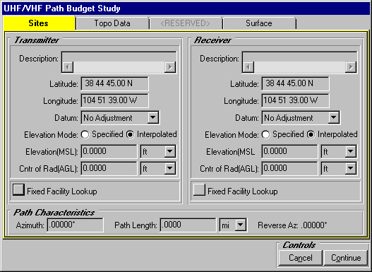
As you can see, the default coordinates for the transmitter and receiver sites are identical. We will use the Fixed Facility Lookup button in BOTH the transmitter and receiver frames in order to access the facility lookup screen where you can view, edit and create new fixed facility data base records for use with this and other TAP programs (see the Fixed Facility Data Base tutorial for more information). When you close the lookup screen, site parameters stored in the current data base record will appear here in the Sites tab of the path budget screen. Recording site parameters in the facility data base allows you to access site information from a centralized data base thereby reducing your data entry time when you use the same site in another TAP program.
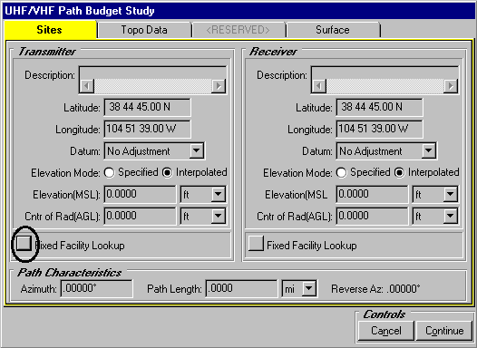
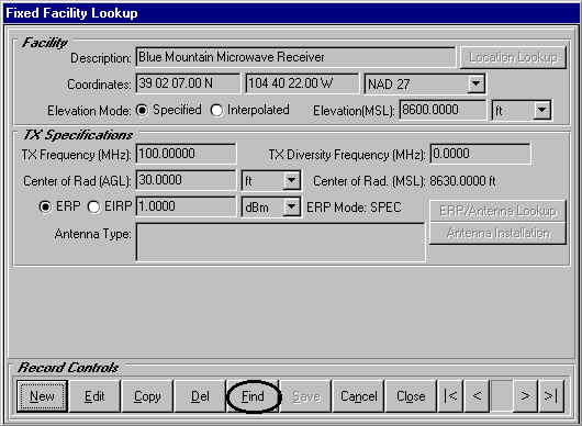
We will use the Fixed Facility Lookup buttons to select transmitter and receiver UHF/VHF facilities from existing tutorial records in the fixed facility data base. Press the Fixed Facility Lookup button in the TRANSMITTER frame first. Your Fixed Facility Lookup program may display the Blue Mountain facility as ours does below. This depends upon the extent to which you have added and deleted fixed facility records prior to running this tutorial. We will navigate to the transmitter record used in this tutorial.
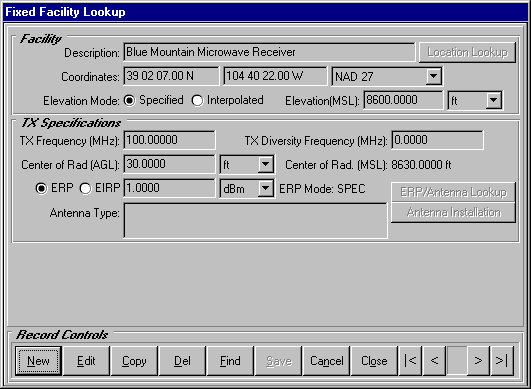
Press the Find button at the bottom of the lookup screen.
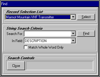
Use your left mouse to pull down a list of facility descriptions in the Record Selection List. Select the Marmot Mountain VHF Transmitter record with your left mouse as we have done. Then press the Select button to reposition the lookup screen to this record.
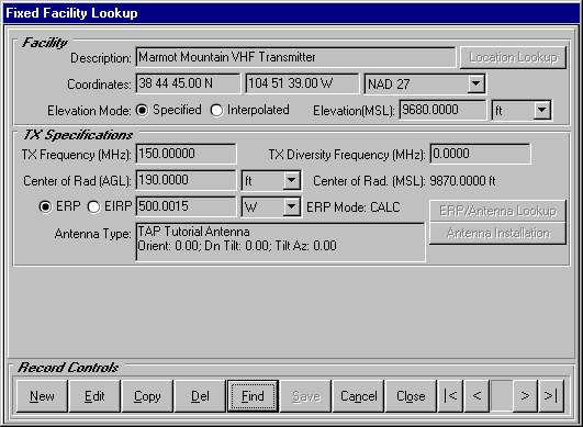
After confirming that the Marmot Mountain site is displayed in the facility lookup program, press Close to close the Find program. Your lookup should appear like ours below. Note that Marmot Mountain has a 150 MHz transmitter operating with a 500 W effective radiated power (ERP). Note also that this facility and the receiver facility that we will select in just a moment have predefined gains, losses and other fields set up for purposes of this tutorial.
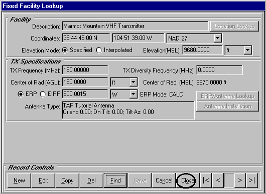
Press the Close button in the lookup to transfer the Marmot Mountain VHF site back to the path budget study screen pictured below.
Now we will select a receiver facility. Press the Fixed Facility Lookup button in the RECEIVER frame first.
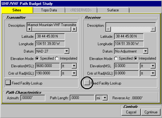
As mentioned above, you may or may not initially view the same facility record (Blue Mountain Microwave) as we do below.
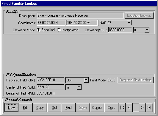
Press the Find button to select Eagle Mountain VHF Receiver from the Record Selection List in the Find program.
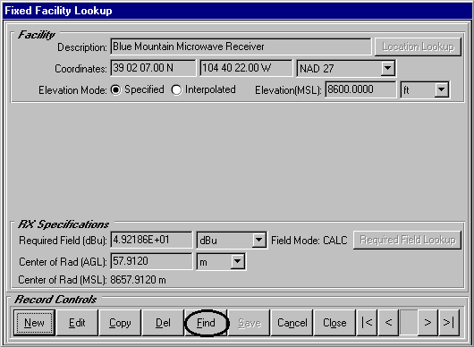
Use your left mouse to pull down a list of facility descriptions in the Record Selection List. Select the Eagle Mountain VHF Receiver record with your left mouse as we have done. Then press the Select button to reposition the lookup screen to this record.
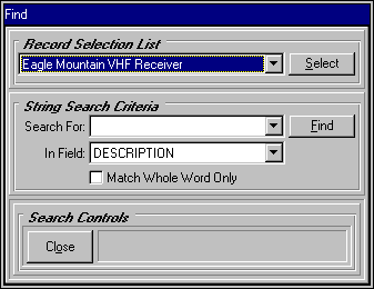
When the facility lookup becomes the active window, the Eagle Mountain site should be displayed.
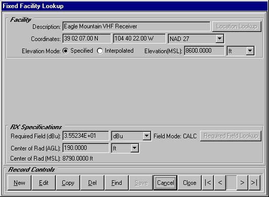
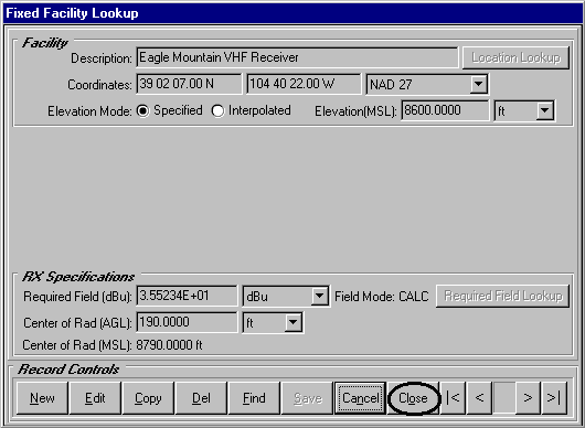
Once the Eagle Mountain VHF facility is the current record in the facility lookup, press Close to transfer your receiver data to the path budget study screen.
As you can see below, TAP automatically calculates the azimuth and path length of the link that we will study.
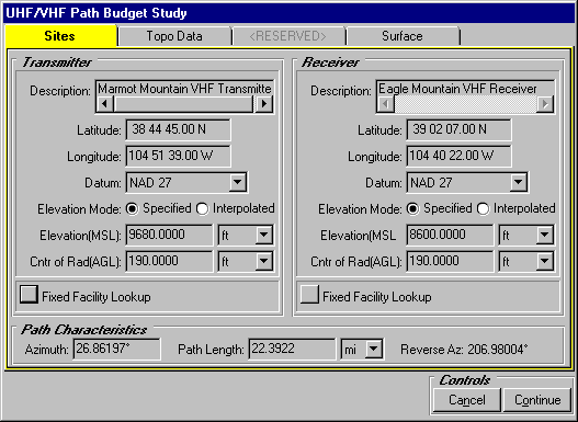
Note that if the elevation mode for each site is "Interpolated" the values shown (9680 and 8600) automatically will be replaced by values for each site from the topographic data base.
Now press the Topo Data tab to set your topographic data extraction preferences.
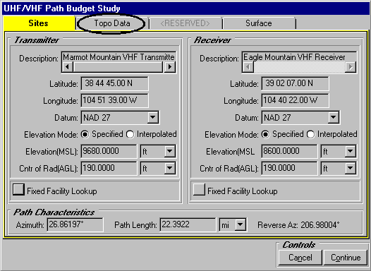
Topographic data is used in the calculation of predicted transmission loss for this path. The TAP terrain data defaults are pictured below. We will modify these settings in the next step.
Use your left mouse to remove the checks from the 30-meter and the 3-second data bases. For purposes of this tutorial, we direct TAP to look for 30-second data only. Compare your topographic preferences to those displayed below.
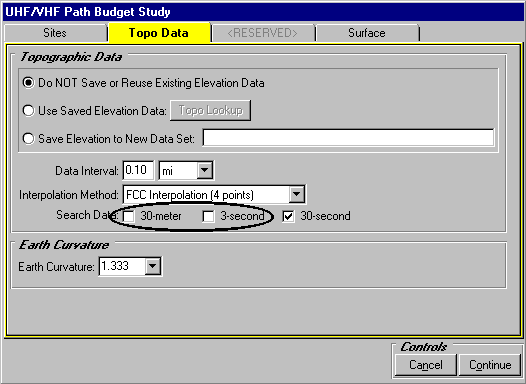
Press Continue in the path budget study screen.
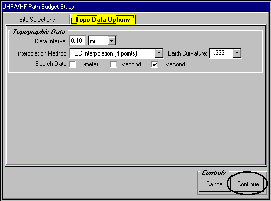
If you have not previously run the link budget for this path, the following warning will be displayed before the link budget tab folders are displayed. Press OK - we will demonstrate the New button below.

When the UHF/VHF Link Budget tab folders appear, you will notice that TAP groups your link budget data fields into three major categories:
TX Specifications
RX Specifications
Path Specifications.
The transmitter and receiver specs folders display summary information about the facilities that form the endpoints of the link. These data fields are "read-only" - they may not be changed in this program. Use your Fixed Facility Lookup program or Fixed Facility Data Base Editor to make modifications to your facility records. The path specifications data fields, however, are not read-only. You will use this link budget program to edit your link budget data base in order to store information specifically related to the path between your facilities.
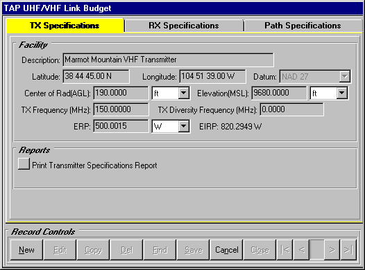
The ERP displayed in the Facility frame of the transmitter specs was calculated by TAP as a function of the transmitter power output (TPO), antenna gain and losses at the transmitter. Press the Print Transmitter Specifications Report button to view the various facility specs used in this calculation. The ASCII text file will be displayed in Notepad. Use the vertical scroll bar at the right to view your transmitter information. You will see, for example, that line and circulator losses were assigned to the Marmot Mountain transmitter.
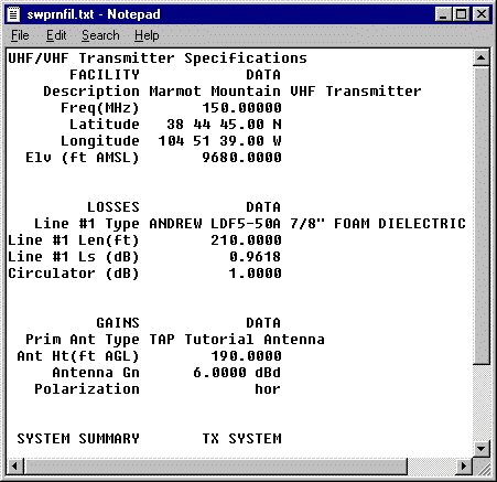
The ASCII text can be printed from Notepad, or saved to another file name, or copied and pasted into another editor, such as Microsoft Word.
Press the Close button at the bottom of the text editor to return to the link budget program.
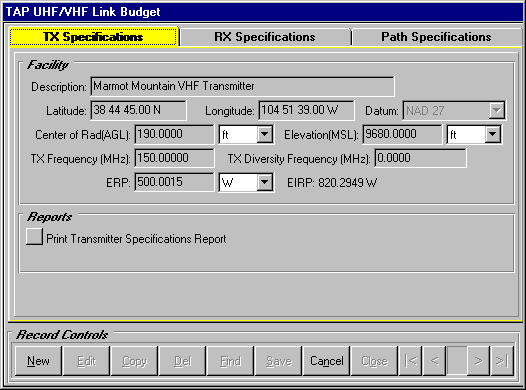
Now use your left mouse to select the RX Specifications tab. The tutorial facility record has a receiver threshold of -113.0 dBm (0.5 m V) assigned to it, as well as several receiver losses that we will view in just a moment.
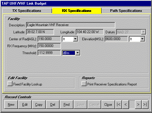
Press the Print Receiver Specifications Report button to view specifications for the Eagle Mountain receiver like those displayed below.
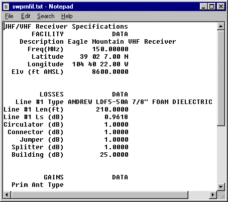
TAP will calculate a required power for this receiver systems as a function of the receiver threshold and receiver gains and losses for the facility. Use the vertical scroll bar at the right of the Text File Editor to view your receiver information. You will see the various circulator, connector, line, jumper and splitter losses built into the Total Loss values displayed in the text editor pictured below. When you scroll down to the bottom of the file, the required power for the receiver system appears.
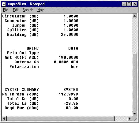
Press the Close button at the bottom of the text editor to return to the link budget program. Now use your left mouse to select the Path Specifications tab. Many of the loss fields displayed in the path specifications tab folders are stored in your link budget data base. You may, for example, wish to contrast the fade margin calculations of both an optimistic and pessimistic path configuration by creating and saving two link budget path records for the same link. When you enter the path budget program for the first time, your only Record Controls options are New and Cancel. We will use the New button to create and edit a new link budget record.
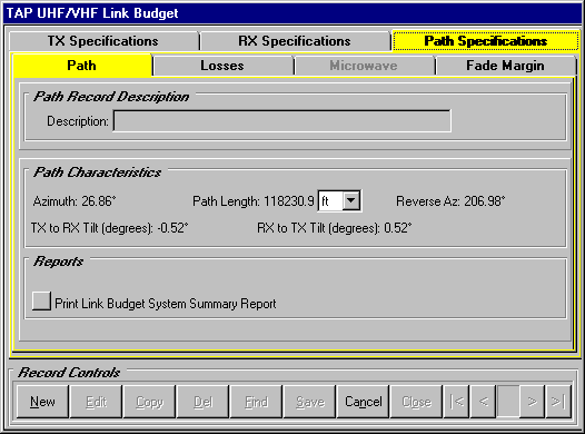
Press the New button to add a record to the link budget data base. The background color of the Description field becomes white indicating that it is editable.
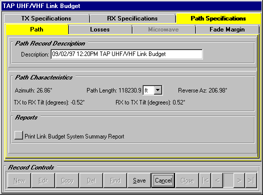
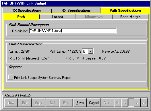
Enter the description "TAP UHF/VHF Tutorial" in the Path Record Description frame.
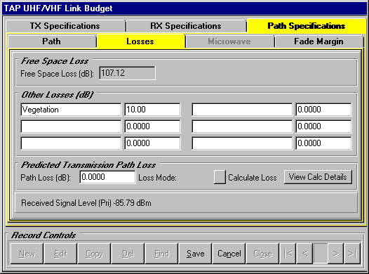
Press the Losses tab to view the Free Space Loss calculated by TAP and six miscellaneous loss fields. The Free Space Loss is a read only value computed as a function of frequency and path length. The Other Losses fields allow you to assign customized losses to this particular path.
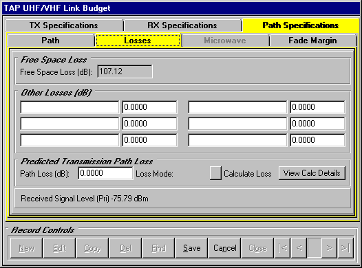
Enter "Vegetation" losses of 10.0 dB as we have done below. When you move off the loss field you will see that the Received Signal Level field is automatically updated to reflect additional losses. The vegetation and other losses added to your path budget record will be incorporated in the fade margin calculations performed by TAP.
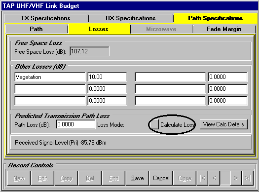
Now we will use TAP to calculate an estimated transmission loss for the path. Press the Calculate Loss button in the Predicted Transmission Path Loss frame.
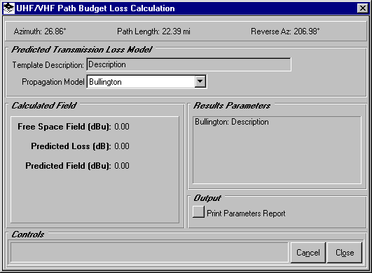
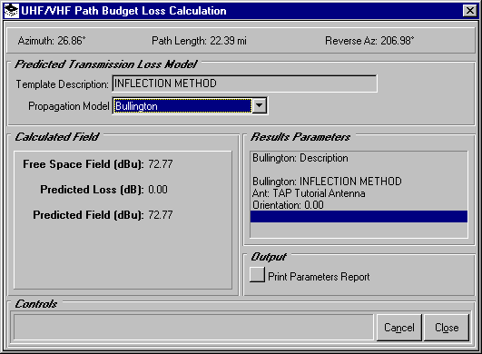
When the UHF/VHF Path Budget Loss Calculation program appears, the Calculated Field frame may display the results of the a field calculation if you had previously used a TAP engineering model to predict transmission loss. If you have not yet used a TAP propagation model to perform a field strength calculation, the loss calculation screen will appear similar to the screen pictured below. We will first use the Bullington model to calculate loss.
Use your left mouse to click the Type of Study list and select the Bullington model. The Bullington Parameters Template lookup is automatically displayed. If necessary, use the VCR buttons at the bottom right corner of this program to navigate to the "INFLECTION METHOD" template pictured below. When you accept the inflection method record, you direct TAP to calculate Bullington obstruction losses using the parameters stored in this template. Consult your TAP technical reference manual for more information about the Bullington model.
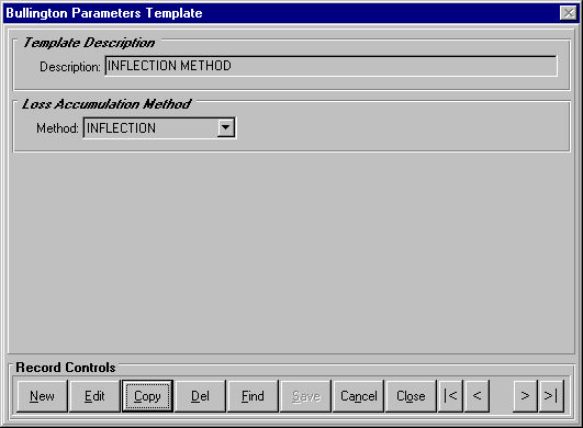
Press Close from the Record Controls at the bottom of the template lookup screen to calculate Bullington obstruction losses using the Inflection method. When the Bullington template disappears, the Calculated Field frame displays the results of the Bullington single field calculation using the INFLECTION METHOD template that we selected. For this path, the Bullington model detected no obstructions and therefore predicted loss of 0.00 dB. We will compare these results to those predicted by the Okumura and Longley-Rice models.
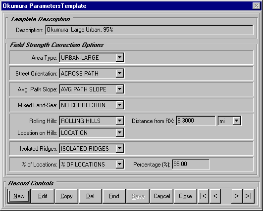
Use your left mouse to change the Propagation Model from Bullington to Okumura. The Okumura Parameters Template lookup will automatically appear. The current Okumura template record may or may not differ from the record displayed below depending on whether you have added your own templates to the Okumura template data base.
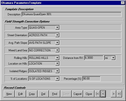
Use the VCR buttons located at the bottom right of this screen to navigate to the "Okumura QuasiOpen 90%" template. Consult your TAP technical reference manual for information about the Okumura correction parameters. You will direct TAP to calculate an Okumura single point field calculation closing the template lookup screen.
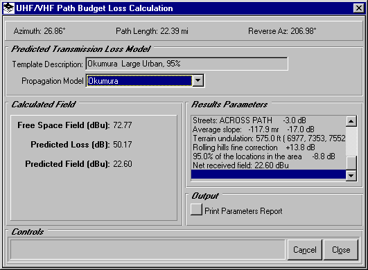
When you have made the "Okumura QuasiOpen 90%" template the current record, press Close to return to the path budget loss calculation screen. TAP will automatically calculate a predicted loss and update the results in the Calculated Field frame. As you can see, Okumura predicts a loss of 50.17 dB for the same path that showed no loss using the Bullington model.
Use your left mouse to change the Propagation Model from Okumura to Longley-Rice. The Longley-Rice Parameters Template lookup will automatically appear. As before, the first Longley-Rice template that appears may differ from the one pictured below. Use the VCR buttons or the Find button to navigate to the "LR Defaults" template.
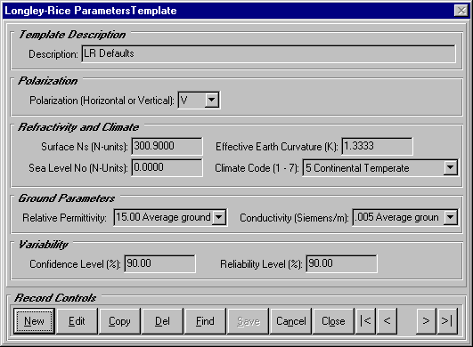
Press Close from the template lookup screen to calculate and display the Longley-Rice predicted field and loss values as pictured below. You will see that in this case the predicted loss is about 9.87 dB resulting in a predicted field of 62.91 dBu at the end of this path.
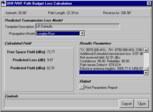
Now let’s view some details of the calculations we just generated. Press the Print Parameters Report button to display the single point field calculation parameters in the TAP Text File Editor.
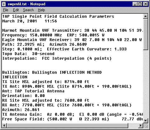
Use the vertical scroll bar to the right of the preview window to move through data written to this file for the three propagation models. Note the estimated transmission loss (9.84 dB) restated at the end of this text file in the Longley-Rice section. This value is greater than the predicted path loss for Bullington (0.00 dB) and less than the loss predicted by Okumura (32.81 dB). These dramatically different results for the same path underscore the major differences among the propagation models in some circumstances. You are advised to understand the engineering model that you rely upon, including its limitations in certain situations. Once again, your TAP technical reference manual is a good starting point to acquire the knowledge needed to make good engineering judgments.
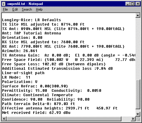
Press Close from the text editor to return to the field calculation program. We will incorporate the 9.87 dB loss predicted with the Longley-Rice method into our path budget study.
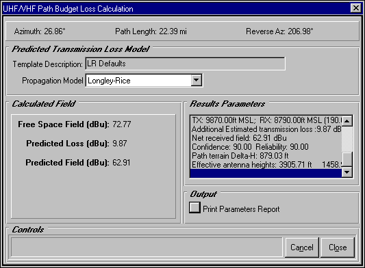
Press Close from the path budget loss calculation program to return to the link budget program. You should now see a calculated path loss in the Predicted Transmission Path Loss frame. The "LR" Loss Mode is a reminder that the Longley-Rice model was used to calculate loss.
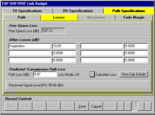
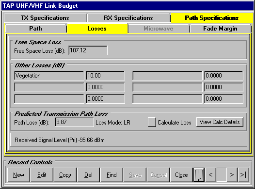
Now press the Save button at the bottom of the link budget program to save these path parameters to the underlying link budget data base. The background colors of the path fields will turn gray to indicate that you are no longer editing a record. The next time you run the link budget program for this path, these path parameters will be available in your link budget data base.
Press the Fade Margin tab to view the received signal and fade margin calculated by TAP. Remember that in addition to the path attenuation values we have just specified, the gains, losses and other parameters defined for the transmitter and receiver facilities have been incorporated in the link budget calculations displayed on this screen.
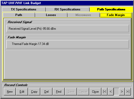
Received Signal Level("RSL") refers to the power in dBm at the receiver input terminal calculated as the sum of Transmitter Power Output plus transmitter and receiver gains (including antenna gains) less transmitter, receiver and path losses.
A Thermal Fade Margin ("TFM") is calculated as the Received Signal Level less the receiver Threshold in dBm. When you use TAP to assist in the design of a UHF or VHF link, you will decide whether the calculated fade margin is sufficient for your application
This concludes the UHF/VHF link budget introduction. When you are ready to exit the link budget program, select the Close button in the Record Controls buttons at the bottom of this program.
Copyright 2000 by SoftWright LLC