Q: How is "aggregate coverage" computed in TAP?
A: The Aggregate Coverage option under the TAP Coverage menu offers several options for combining TAP tile studies.
This article discusses the Aggregate Coverage calculations in TAP. The Aggregate Calculations have been replaced in recent versions by the Composite Coverage calculations.
Also note that the user interface examples in this article show older versions of TAP. While the principles of the Composite (or Aggregate) coverages are still accurate, you can see the current user interface in other FAQ, such as Composite Studies in TAP6.
Other topics of interest for Composite studies:
Aggregate Coverage Demonstration
How can I make my Composite studies run faster?
The TAP Aggregate Coverage Program
The TAP Aggregate Coverage Program combines the results of two or more tile studies into one study that you can view using the TAP Tile Threshold plotting program.
For a detailed example of the calculations used in the Aggregate Coverage program, see the Aggregate Coverage Demonstration article.
In the process of combining files, TAP will perform specific operations on selected tile field strength coverage or shadow studies. The contents of the resulting tile study file will differ from the input files in some pre-defined manner. Math operations to generate aggregate coverage values will operate on coincident tile regions, that is, tile regions with identical geographical limits and incremental distances between points in the region. The transmitter site coordinates, however, need not be the same.
This program would allow you to evaluate coverage over a tile area from different transmitter sites, or to evaluate the coverage from a single site with different facilities (tower heights, antenna patterns, etc.).
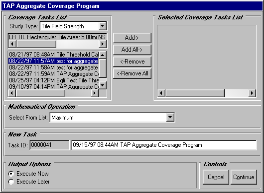
Aggregate Coverage Program Design
Using the Aggregate Coverage Program, you will first select either a Tile Field Strength or a Tile Shadow Study Type. You will then select and move the studies you wish to combine ("input files") to the Selected Coverage Tasks List using the Add buttons. Each selected study must cover an identical tile coverage region, although the transmitter locations for the studies may differ.
After the studies have been selected, you will direct TAP to combine your input files using one of several Mathematical Operations:
The Best Server function evaluates the value from each input study at each tile point. The maximum coverage value at each tile point would be written to the results file ONLY IF the differences between this value and all other computed coverage values at the same location are greater than or equal to a user-defined value (a "capture margin"). In this manner, you will build a condition of sufficient isolation between signals at each field strength point on the tile. Any point without the specified separation between the signal levels would be considered a point of no service, regardless of the magnitude of the highest signal.
As an example, suppose you wish to generate a best server study from four input field strength tile studies. Assume further that you have specified a desired capture margin of 10 dB. In the picture below, the 75 dBu field strength value at the center of the tile region will be written to the results file because it exceeds the next highest value (65 dBu) by 10dB.
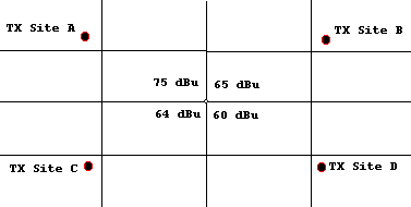
On the other hand, if you had specified a capture margin of 15 dBu, a "dummy value" would be written to the results file indicating that the best server conditions were not met. You will then assign a particular color or fill pattern to each point that meets the best server criteria and view these points in a TAP Threshold plot.
Combining multiple coverage studies into an aggregate for the purposes of a simulcast study involves consideration of both the magnitude and relative phase of each component signal at each location.
Given the computed field strength at each tile location, the relative phasing of each component is computed based on the wavelength and distance from the respective transmitter to the point under consideration. Assuming all transmitted signals originate in phase, one facility (arbitrarily the first in the list) will be considered the reference phase. The distance from that transmitter to the point is computed in wavelengths. Then for each other transmitting facility, the difference in the wavelength distance from the reference phase is computed. Then the field strength component from that other transmitter is adjusted by the Cosine of the phase difference. For example, a second transmitter that is an even number of half wave-lengths phase difference would be added, while one that is an odd number of half wave-lengths would be subtracted. The net field strength recorded would be the vector sum of all the components.
Separate Transmitter Phasing Values
In addition to the computed distance-related phase difference, you can also assign a relative phase value (in degrees) or a "launch delay" (in microseconds) to each of the transmitters. This value would be a hardware-related variable that represents the total phase value for each transmitter, including factors such as transmission line lengths and electronically adjusted phasing.
As an example, consider two transmitters, A and B, with the following parameters relative to a receive location under consideration:
| Transmitter A | Transmitter B | |
| Frequency (always the same for a simulcast system) | 450 MHz | 450 MHz |
| Computed field at RX | 55 dBu | 49 dBu |
| Distance to RX | 11 km | 15 km |
| Signal Phasing | +15° (+0.04166l ) | -30° (-0.0833l ) |
We can arbitrarily designate Transmitter A as the reference. (Normally the phasing of the reference would be zero, but for this illustration use the values shown above.)
The wavelength in meters is:
![]()
![]()
Computing the distance from each transmitter to the receive location in wavelengths:
Transmitter A: 11km /.667meters = 16,491.75412l
Transmitter B: 15km /.667meters = 22,488.75562l
Since Transmitter A is the reference, we need the difference in phase between that reference and the arriving signal from Transmitter B. This difference is computed considering both the signal phasing at the transmitter and the phasing effect of the distance to the receive site. The difference between phases is the phase of B minus the phase of A:
D j = (-.0833l + 22,488.75562l ) - (.04166l + 16,491.75412l )
D j = 5996.876539l
(Without tx phasing)
D j = (-.0833l + 22,488.75562l ) - (.04166l + 16,491.75412l )
D j = 5999.0015l
We only need be concerned about the non-integer portion of wavelength differences. (Signals with phase differences that are an integer number of wavelengths would be perfectly in phase.) Considering the fractional wavelength difference:
D j = .876539l · 360 ° /l
D j = 315.55404°
D j = . 0015l · 360 ° /l
D j = 0.54°
The composite field is the sum of the reference value, plus each other component added as a vector considering the phase difference. First, the computed field strength magnitude of each component must be converted to m V/m so the values can be added:
Transmitter A: 55dBu = 20 Log (E) => Ea = 562.34m V/m
Transmitter B: 49dBu = 20 Log (E) => Eb = 281.84m V/m
The composite signal is:
Ea + Eb· Cos(D j )
562.34 + 281.84· Cos(.54° ) = 844.167m V/m = 58.53 dBu
562.34 + 281.84· Cos(315.55404° ) = 763.549m V/m = 57.66 dBu
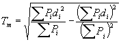
The combined effect of multiple simulcast signals can also be computed using the "Delay Spread" factor.
This factor is given in Handbook of Land-Mobile Radio System Coverage (Garry C. Hess, Artech House, 1998, p. 131) as a function of the power P and the delay d (based on distance) for each received signal:
In TAP, when you select the Simulcast (Delay Spread) type of Aggregate Coverage, you must enter two parameters:
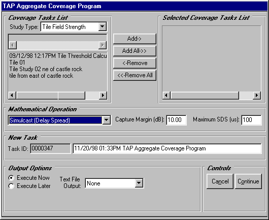
The "Capture Margin" is the value described under "Best Server" above. If any one signal exceeds all others by this value, then this single signal is sufficient to be recognized by the receiver, and the point in question is assigned this value.
If the capture margin criterion is not met, the spread value is computed from the equation from Hess above. The "Maximum SDS" is the maximum permitted delay value. If the computed delay spread exceeds the maximum value, then the point is considered to have no usable signal. If the computed delay is less than the maximum specified delay, the signal at the point is the computed sum of the received power of the signals (added linearly).
Copyright 1999 by SoftWright LLC