Microwave engineers sometimes encounter unsatisfactory point-to-point links with clear line of sight, clear Fresnel zone, and predicted received signal strength that should provide high reliability. The problem may be a reflection point along the path causing destructive multi-path interference. The Reflection Analysis module searches for possible surface reflections for the given path and evaluates the potential impact on the link. The presence and location of reflections depend on the terrain profile, the TX and RX antenna heights, the frequency, and the earth curvature (i.e., K) parameter. The magnitude of the reflection, relative to the direct signal, depends of the clearance of the reflected path from the TX and the RX, the reflection coefficient of the ground at the reflection point, and the phase of the reflected signal, relative to the direct signal.
Click here to view a TAP 7.5 Reflections Analysis tutorial video.
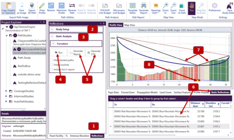
As shown above, the new Reflections Analysis Module functionality is accessed from a new user interface tab available on the Transmitter side of a Path Study. On the “Reflections” tab (1), configure (2 and 3) and run (4) your reflection analysis, and produce reports (5). After reflections are computed, the tabular results are shown on the “Static Reflections” tab (6). The currently selected reflection is drawn on the path profile (7). Markers (8) are drawn along the horizontal axis to indicate reflection points. The currently selected point is shown highlighted in yellow.
The new Reflection Analysis component is a significant upgrade over the legacy capability that was available in TAP6. The new capability supports up to two transmitter and two receiver antennas located respectively at the transmitter and receiver fixed facility site locations. For the reflection coefficient, users can select the “Fixed Value” option to set and use a fixed reflection coefficient (value in the range [0,1]). Alternatively, users may select the “Use Land Cover Data” option to define reflection coefficients for each land cover type in the currently selected land cover data. TAP will automatically generate this list from the land cover types along the path for users with the Land Cover Module licensed.
Whereas the legacy Reflection Analysis capability only evaluated for reflections at topo points, the new capability also searches between the topo points. The new Reflection Analysis component allows the user to select a range of effective earth curvatures, K. For a user-defined K range, TAP finds reflection points for (1) the minimum and maximum K values; (2) any topo points with reflections falling in this range; and (3) any worst-case reflections in this range corresponding to even Fresnel zones intersecting the ground. The calculated reflections account for TX and RX antenna discrimination and the reflection coefficient. The TAP 7.5 built-in help contains step-by-step instructions for how to setup and run Reflection Analysis.