Training Question:
Do I Have Line of Sight on This Path?
Given a transmitter site and a receiver site, determine if
line of sight exists, and if not, estimate how much loss will
be introduced based on the obstacle(s).
The two sites are:
Cheyenne Mountain Test Facility
38 44 45.00 N
104 51 39.00 W
Castle Rock Test Site
39 25 39.00 N
104 52 00.00 W
(Both of these sites are included in the Fixed Facility data
base supplied with the TAP demo.)
From the Path menu, select "Path Profile":
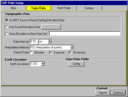
The TAP Path Setup form is displayed:

- Enter the site description, coordinates, and datum,
OR use the Fixed Facility
Lookup button to find each site in the data base.
- If the elevation of the site is known from a map, survey,
etc., click the Elevation Mode "Specified" option and
enter the elevation. Otherwise, click the "Interpolated"
option and the program will search for the elevation from the
topographic data files.
- Enter the height of the center of radiation Above Ground
Level for each antenna.
Click the Topo Data tab on the form:
Click the "Path Profile" tab on the form:
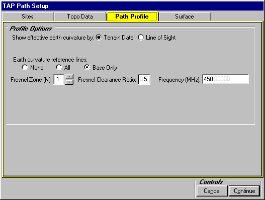
- Select the "Terrain Data" option for earth curvature.
- Select "Base Only" for reference lines.
- Select "1" for the Fresnel Zone.
- Set the Fresnel
Clearance Ratio to 0.5.
- Set the Frequency to 450 MHz.
Click the "Surface" tab on the form:

Click the Continue button.
The path profile is displayed:
- You can move the mouse along the path to see an estimate
of the Bullington
knife-edge loss (base
on Fresnel zone penetration) of obstacles along the path. For
example, the peak at 33.10 miles introduces a loss of approximately
8.52dB.
- You can add text
labels to the drawing.
- You can add text
file information to the drawing.
- In TAP 4.3 and later, you can set the properties (color,
line width) of different parts of the drawing.
- In TAP 4.3 and later, you can export
the path distance and elevation values to an ASCII file.
- In TAP 4.3 and later, you can save
the drawing to your own file name.
Copyright 2000 by SoftWright LLC